")
Design Guide for The Preparation of Piping Design Documents
1. Piping General Arrangement Drawings (Piping G.A.’s)
2. Piping Isometrics
3. Piping Material List
4. Piping ISO-System Drawings
5. Rules for Executing Piping Design Work for Revamp Projects
6. Instructions for Checking Piping Documents
Attachments
A. Production Flowchart of Pipng Documents
B. Drawing Symbols
C. Nozzle Data
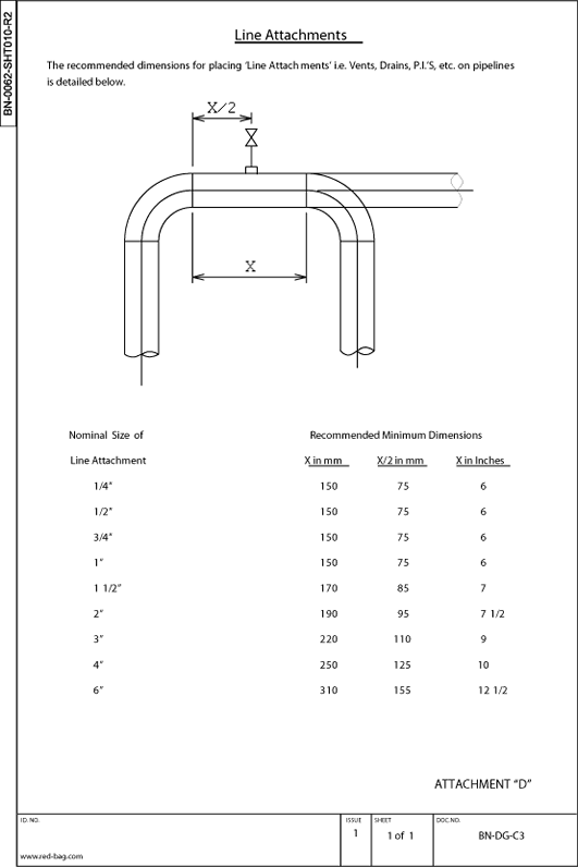
D. Line Attachments
E. General Abreviations
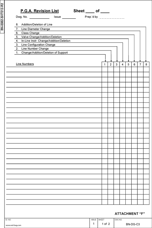
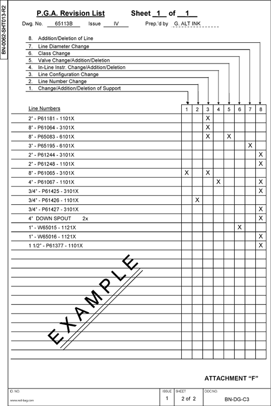
F. Piping G.A. Revision List
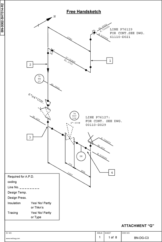
G. Free Handsketch for APD-ISO
H. System Drawings Example
J. Piping Material List
NOTE:
This guide lays down the standard requirements of Red-Bag.
Client’s requirements shall take priority over Red-Bag's
standard methods, when specifically directed.
1. Piping General Arrangement Drawings (Piping G.A.’s)
Preparatory Work to Produce PIPING G.A.’s
Prior to being able to produce any adequate PIPING G.A. in an efficient manner, it is essential that sufficient piping studies are prepared with the aid of agreed/approved plotplans, PEF’S, PEUF’S and Piping Data Sheets (line designation tables).
These piping studies shall then be used as “coordination studies” to inform/collect comments from other disciplines such as process engineering department, projectengineering department and all relevant design engineering departments.
If on a project a detail design model is provided, these coordination studies shall also beused to execute further design work on the model.
The interrelation of PIPING G.A. preparation with the plotplan, the piping studies, the model(if any) and the piping handsketches is shown on the production flowchart for piping designdocuments. See Attachment A.
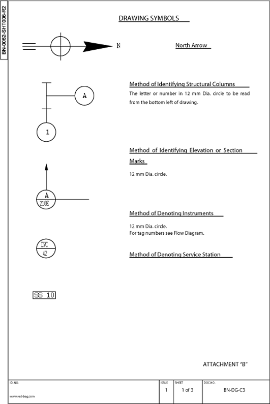
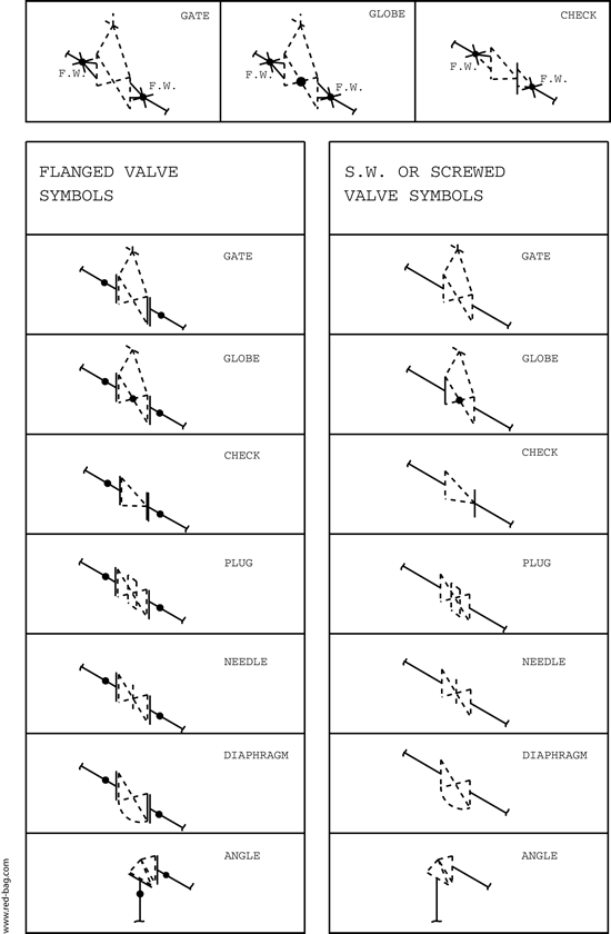
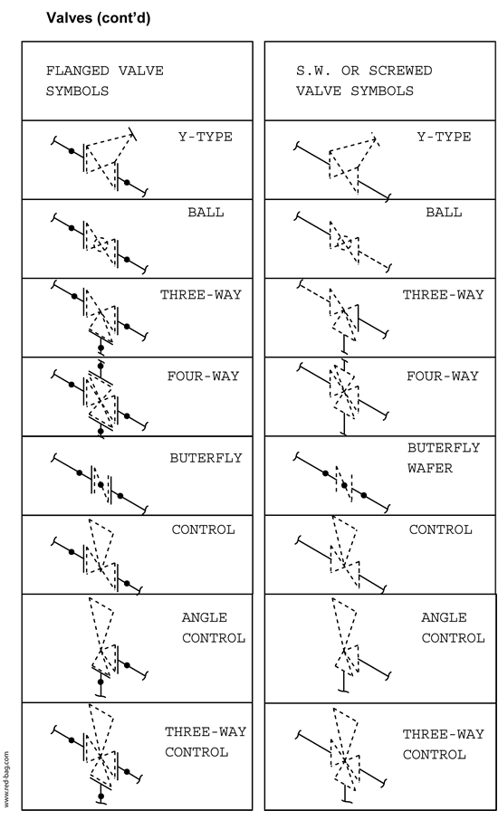
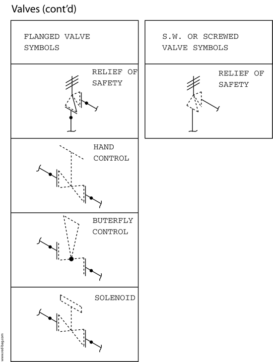
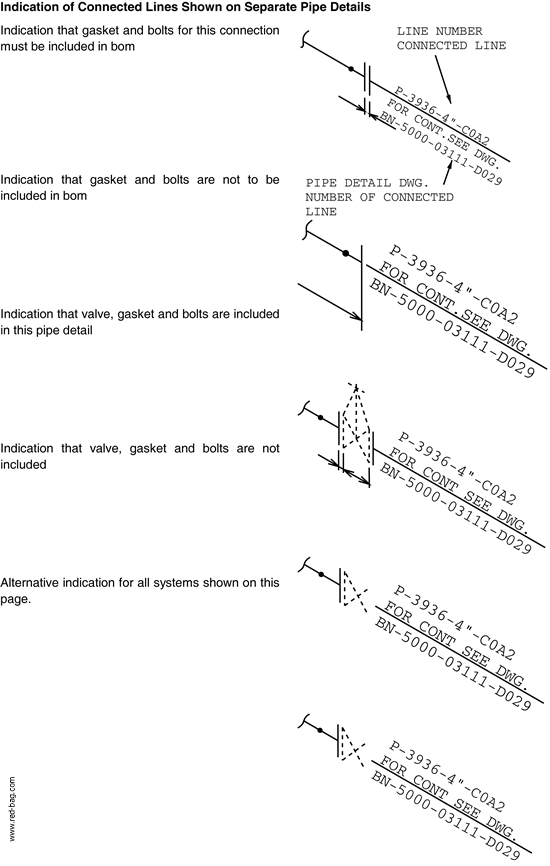
Drawing symbols shall be in accordance with Attachment B.
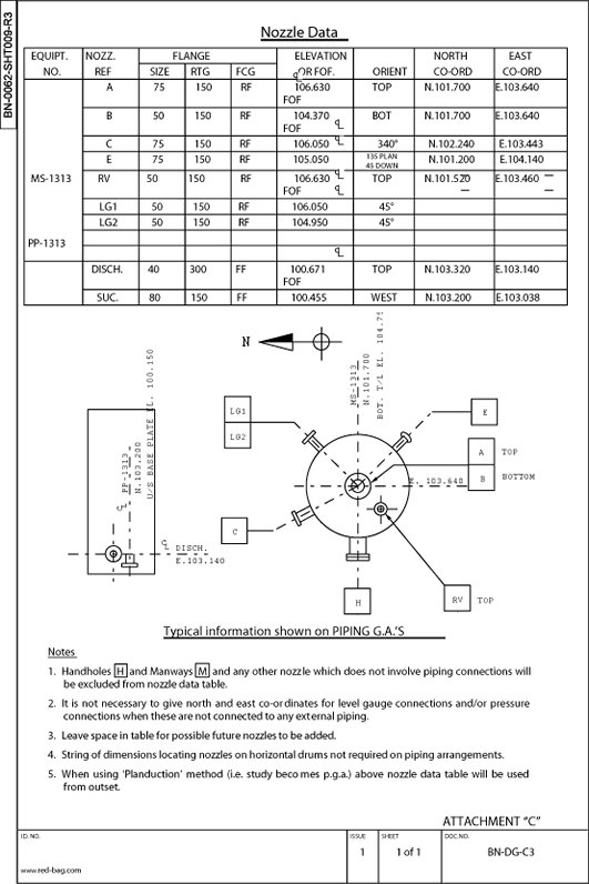
Nozzle data shall be in accordance with Attachment C.
Line attachments shall be in accordance with Attachment D.
General abbreviations shall be in accordance with Attachment E.
Revisions to piping g.a.’s shall be indicated on piping g.a. revision lists per drawing issue.See Attachment F. Revisions to PIPING G.A.’S shall at all times refer to line numbers.PIPING G.A.’S shall under no circumstances be re-issued for any change which is notrelated to piping. Such a change in itself may be a necessity. It is not a reason for re-issueof the drawing unless/until it affects the piping layout.
Note: the use of clouds on PIPING G.A.’S to indicate revisions is prohibited.
Procedure for Presentation and Numbering of Documents andDrawings.
Drawing instructions
Size of sheet
A. A1 format (594 x 841) sheets shall be used.
B. The use of other than A1 format shall be discussed with the squad leader.
Scale
A. 1 : 33 1/3 shall normally be used for piping within an area, also for unit pipe racks.
B. 1 : 75 shall be used for yard rack piping plan views.
1 : 33 1/3 scale may be used for sections through rack.
C. Where there seems to be a reason for any other scale, the matter should be
discussed with the piping squad leader.
D. Dimensions shall be given in mm. No dimension less that 1 mm shall be used.Printing of notes etc. Shall not be less than 3,5 mm high. To obtain a readablelettering for microfilming.
E. A figured scale stick of 100 mm long shall be preprinted on the vellum in the marginof the drawing to indicate original scale.
Workspace
A plan shall be placed on the drawing sheet the same way it appears on the plotplan (i.e.same north arrow as plotplan). The north arrow shall be placed on all plans in the upperright hand corner of the sheet, using the standard north arrow sticker. See attachment b,sheet 1.
Fixed Items
Fixed items such as match lines, steelwork, platforms, cable trays, equipment outlines shallbe drawn on the reverse side of the vellum (equipment nozzles shall be considered as partof piping). The squad leader or his designate shall check completeness and accuracy ofscale of all basic piping g.a.’s prior to designers/draftpersons drafting the piping on the frontside of the vellum.
The scope of the drawing is determined from the “key-plan” of piping drawings. Confirm thecut off elevation and drawing title from the drawing index, prepared by the squad leader.
General Notes
General notes, reference drawings and tables shall be included in the area above the titleand the issue block.
The following notes will appear on the “a” or grade drawing for each piping area.
A. Badger high point of grade elevation = 100.000 mm is equal to (Client’s Name)
elevation _ _ _ _ _ _ _ _ _ _ mm.
B. For general notes and reference drawings see area identification plan BN- .... -00102.
The Nozzle Table
The nozzle table is placed at the top right hand corner of the drawing sheet. A completedexample is to be found in Attachment C. Maximum use must be made of abbreviations,reference Attachment E.
Plan Views
Dimension lines defining the location of columns, steelwork and equipment shall be placed, if possible, outside the match lines. Dimension lines for piping can be placed, if moreconvenient or clear, inside the match lines.“Closing” dimensions will be given, the rule is “do not over dimension”. If part of a layout canbe clearly shown with two dimensions, do not give four. However, to suit apd requirements,“string” dimensions for piping is mandatory. All elevations of pipe will be center line of pipe.
All dimensions and notes on a drawing shall be read from the bottom or right hand side ofthe vellum.
Design Information
Designers, draft persons, and checkers shall incorporate the latest information on a drawingby constantly checking the following document masters:
Flow Diagrams and Line Tables (Data Sheet Piping)
Plotplans and Key-Plans
Coordination Studies (Initial Plot Studies)
Stress Comments and Sketches
Equipment Drawings
Structure and Platform Drawings
Foundation and Underground Drawings
Piping Specifications
Engineering Design Guides (e.g. C1 - Issued for Job)
Job and General Standards
Pipe Sketches for Calculations by Process Department.
Should it be necessary to depart from the arrangement shown on the flow diagram orcoordination studies, the
squad leader shall be informed. If the change is agreed proceedas follows:
Flow Diagrams
The change shall be agreed with the Project Engineer, and be recorded on the master flowdiagram.
Coordination Studies
The piping squad leader shall agree to the change, and inform other sections.
Design Features
Outline all structural framing including platforms, etc. Also locate and identify structuralcolumn lines in accordance with the plot plan. Show the elevations of all platforms. Drawunderground drain tundishes, electrical- and instruments cable trays and trenches. Indicateall local electrical- and instrument cabinets and junction boxes.
For method of identifying structural columns, see Attachment B, sheet 1.
Outline all equipment with the minimum of detail, pumps shall show outline of base plate,and all nozzle connections. Identify and locate all equipment in the same way as shown onthe plot plan. Withdrawal and drop out areas are to be clearly indicated.
Identify pipe lines by line number, size and class as shown on the flow diagram, locaterelative to equipment and structural columns, elevate to bottom of pipe (bop) for racks andbanks of pipes. All piping to be shown as single line, up to and including 12” diameterdouble line piping for 14” diameter and larger.
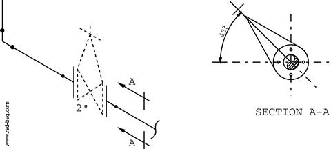
Sections and elevations shall be kept to a minimum and only be drawn to clarify pipingmanifolds and control sets, etc. In case of doubt as to the need of a section or elevation, thepiping squad leader shall be consulted.
The elevation or section mark shall show, in the upper half of the 12 mm diameter circle.The last three digits and suffix letter of the drawing number on which the elevation orsection appears shall show in the lower half of the 12 mm diameter circle. To be read fromthe bottom of the drawing, see Attachment B, Sheet 1.
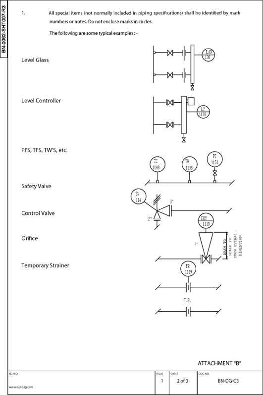
The following items are to be numbered, noted or shown on the drawings:
Control Valves
Orifice Assemblies
Relief Valves
All Instrument Connections - See Attachment B
Gauge Classes
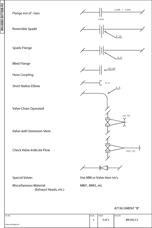
Miscellaneous Material (mm)
Position of Hand Wheel on all Valves 2” and Larger
Extended Stems on Valves
Chain Operated Valves (Ch.Op) Spades and Blinds Temporary Strainers Steam Traps Exhaust Heads Short Radius Elbows Flanges if Different from Line Class Service Stations
All symbols for valves and piping fittings, etc., Are to be in accordance with Attachment B. Control valve manifolds to conform to BA-CD-5M/6M where possible.
Pipe rack drawings to be cross referenced by use of a key-plan of the rack, or same keyplanas used for other drawings as applicable, with the area covered by the drawingidentified.
Other Drafting Necessaries Piping areas on all drawings to be bounded by “match lines”. The coordinates of these linesare to be shown, with following note adjacent to the match line: for continuation see drawing BN-....-00111A, etc. All piping crossing match lines to be identified and dimensioned.
The draft person is to consider all items listed in the instructions for checking of pipinggeneral arrangement drawings.
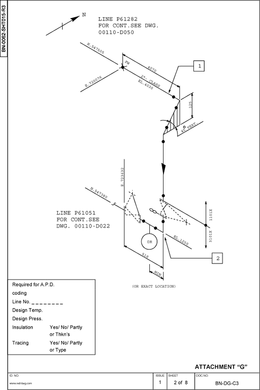
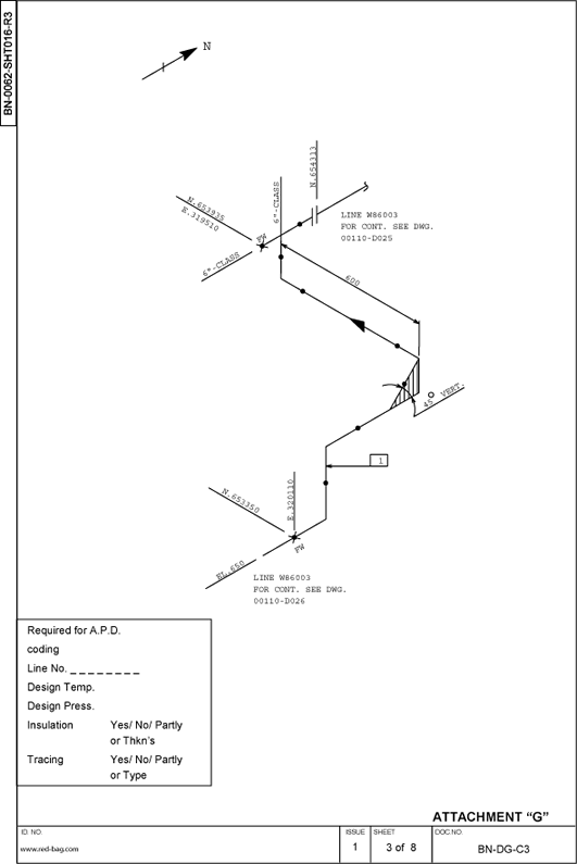
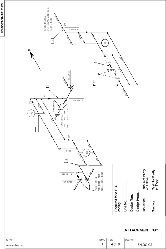
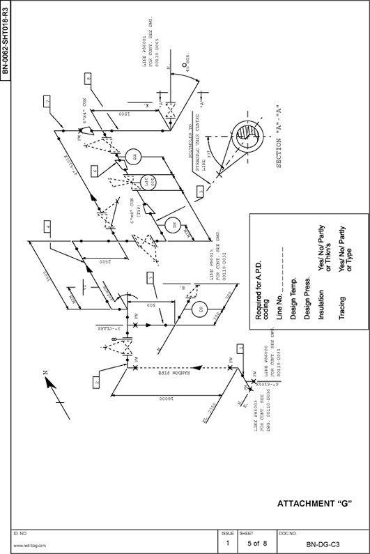
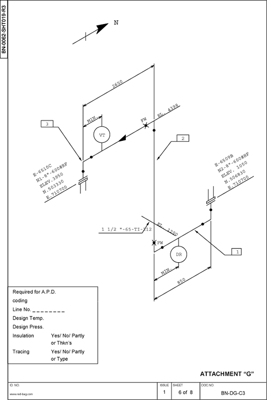
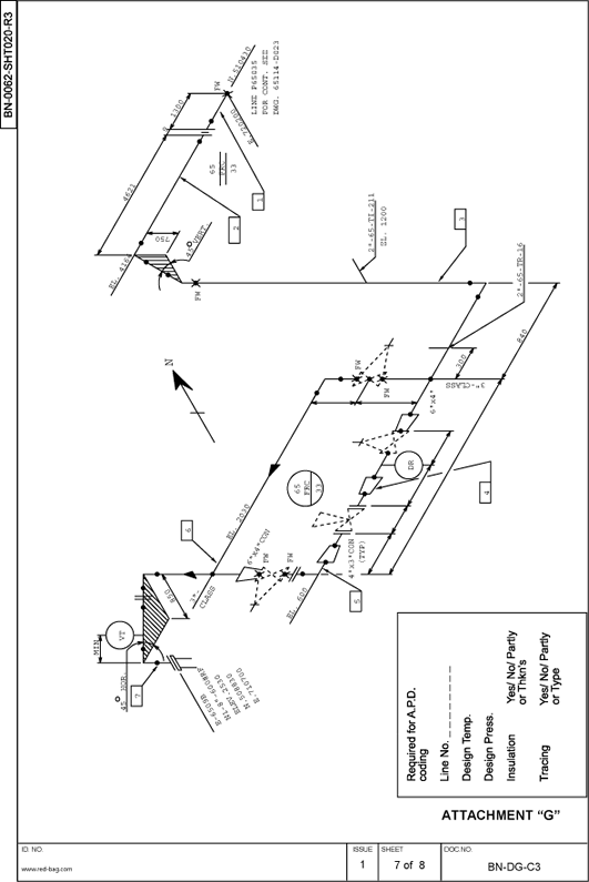
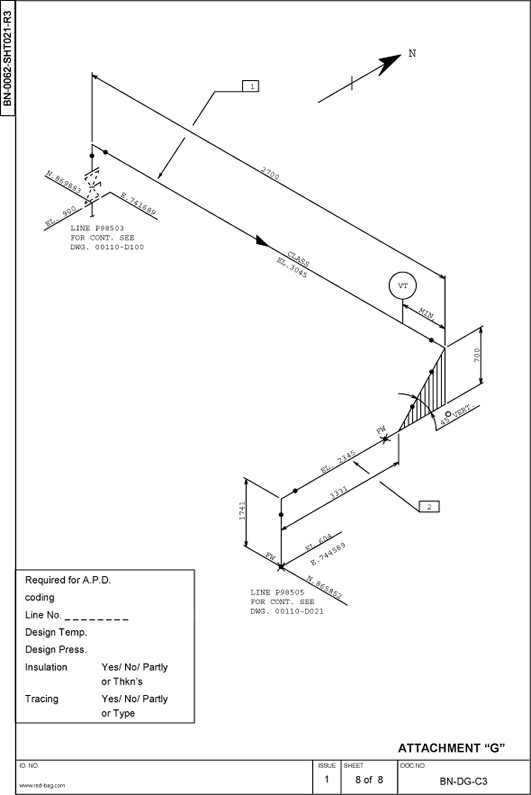
For the dimensioning technique for use with apd, see Attachment G.
After “certified” issue and subsequent issues, all changes that affect the pipe fabricator shallbe indicated on the revision list - see Attachment F.
Additional information to complete the drawing
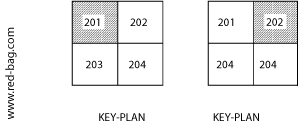
Key-plan
A. Locate in upper right hand corner of the sheet
B. Do not draw to scale, do not show equipment etc.
C. Indicate north arrow
D. Cross hatch area involved (see example):
Reference Drawings
A. Locate under “General Notes”, allowing ample space for more notes to be added.
B. The drawings and the order in which they shall be listed shall be as follows:
Plotplan
PEF’S/PEUF’S
Lines at Lot Limits (List only on area drawing adjacent to Lot Limit)
Remainder of Area Piping Arrangement Drawings
Adjacent Areas (Lead Sheets only)
Pipe Details
List of Field Materials
Sewer and Underground Piping
Instrument Piping
Steam Tracing (if any)
Location of Service Stations
Pipe Supports
Foundation Location Plan
Miscellaneous Pump Piping
Tie-in Lists (if applicable)
Demolishing Drawings (if applicable)
Redundant information on PIPING G.A.’S
Redundant information on PIPING G.A.’S include any information extraneous to piping, such as instrument junction boxes, etc.
Much time is spent by draftpersons putting center line of pipe many times on drawings. To
avoid this, one general note shall be made on the drawing to effect that all elevations are
center line of pipe unless otherwise shown.
Notes, such as those on insulation of dummy legs, shall not clutter up piping g.a.’s, but shall
be included in specification instead.
Sections shall be used at all items in lieu of details, which shall be avoided on piping g.a.’s,
if a detail is needed, use a section.
2. Piping Isometrics
In general pipe details are required for carbon steel piping of 2” and larger and for stainlessor alloy steel piping all sizes, including inside coated and jacketed pipe.
The squad leader will give additional rules as far as special cases are concerned, for instance:
- Screwed galvanized piping 2” and larger.
For certain countries (east european), the abovementioned requirements may vary, instructions how pipe details should be prepared in these cases will be given by the coordinator for each project. Pipe details will be drawn in isometric projection unless this would make the pipe detail unnecessarily complicated, i.e. stand pipes. Pipe details are not drawn to scale, but if possible all spool pieces should be shown in
proportion to each other on the particular sheet, as long as it does not effect not good clarity.
Methods of Presentation
To distinguish between material needed for the actual pipe fabrication in the pipe shop and erection of field material, the shop fabrication items are represented by a full (not heavy) line ______________ , and erection components like valves, blind flanges etc. are drawn dotted --------------.
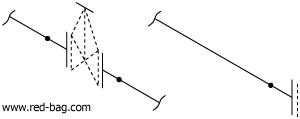
Continuation runs on terminal points or branches should only be extended to a minimum and are shown by a full thin line. Descriptions and identifications of these points are given on page 10.
Continuation runs of field fabricated pipe will be shown dotted if to be included on the isometric.

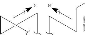
Pipe details shall have the same north orientation to the furthest possible extent.

Branch Connections
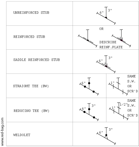
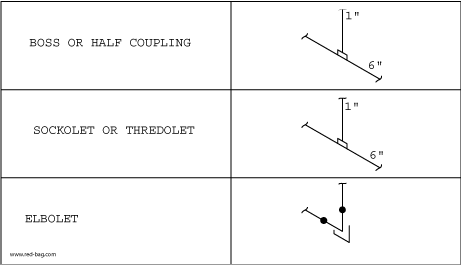
Fittings

Flanges

Miscellaneous

Note: The type of flanges to be used depends on pipe class.
Valves
In general all APD sketchees must show spindle orientation (needed for coding).
| ASSY | - | Assembly | RED | - | Reducer | |
| BC | - | Bolt Circle | RF | - | Raised Face | |
| BL.FL | - | Blind Flange | RFSF | - | Raised Face Smooth | |
| BW | - | Butt Welded | Finish | |||
| CI | - | Cast Iron | RO | - | Restriction Orifice | |
| CON | - | Concentric | RP | - | Random Pipe | |
| CS | - | Carobon Steel | SC | - | Sample Connection | |
| CTF | - | Cut to Fit | SCHED | - | Schedule no. of Pipe | |
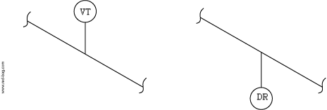
| DR | - | Drain | SCR'D | - | Screwed | |
| DWG | - | Drawing | SGO | - | Spur Gear Operated | |
| ECC | - | Eccentric | SML | - | Seamless | |
| EL | - | Ellevation | SO | - | Slip-on-Flange | |
| FB | - | Fitting Bound | SP.BL. | - | Spectacle Blind | |
| FF | - | Flat Face | SR | - | Short Radius | |
| FLGD | - | Flanged | SS | - | Stainless Steel | |
| FOB | - | Bottom Flat (Ecc.Red.) | SW | - | Socket Weld | |
| FOF | - | Face of Flange | SWGD | - | Swaged (Nipple) | |
| FOT | - | Top Flat (Ecc.Red.) | TOS | - | Top of Steel | |
| FW | - | Field Weld | TS | - | Temporary Strainer | |
| GALV | - | Galvanised | TYP | - | Typical | |
| GO | - | Gear Operated | VERT | - | Vertical | |
| HORZ | - | Horizontal | VT | - | Vent | |
| LR | - | Long Radius | WN | - | Welding Neck Flange | |
| ML | - | Make-up Length | ||||
| MOV | - | Motor Operated Valve | ||||
| NPT | - | National Pipe Thread | ||||
| Abbreviations to Be Used With Straight and Swarged Nipples: | ||||||
| LB/ST | - | Large end Beveled/Smal end Threaded | ||||
| LT/SB | - | Large end Threaded/Small end Beveled | ||||
| LB/SP | - | Large end Beveled/Small end Plain |
for
|
|||
| LP/SB | - | Large end Plain/Small end Beveled |
Swaged Nipples
|
|||
| LP/ST | - | Large end Plain/Small end Threaded | ||||
| LT/SP | - | Large end Threaded/Small end Plain | ||||
| OP/OT | - | One end Plain/One end Threaded | ||||
| OP/OB | - | One end Plain/One end Beveled |
for
|
|||
| OB/OT | - | One end Beveled/One end Threaded |
Straight Nipples
|
|||
| BEP | - | Both Ends Plain | ||||
| BET | - | Both Ends Threaded | ||||
General Notes on Pipe Details (Isometrics)
The extent of piping on an isometric shall be confined to the line number and the piping material specification.
Furthermore, decisions be made by the squad-leader about iso’s running from one area to another, special attention should be taken for piping materials, a clear decision should be made in which area it will be included in the take-off, to avoid double ordering.
It is not good practice to stop a line at the matchline, providing a field weld, as this would call for extra welds, natural break points should be used, such as flange connections, elbows, etc.
Try to avoid detailing field run piping (small bore piping) that connects to a shop fabricated spool, just refer to the plan drawing.
Valve stems should be omitted, but if reorientation of boltholes would be required a supplementary sketch showing bolthole details and stem orientation should be provided.
Where pipe class changes occur, within one line number, it should be indicated on the isometric.
Only separate details where else a mixture of carbon steel and alloy steel or carbon steel and stainless steel occurs.
Describe any out of class materials such as 4 way valves mating flanges etc. Give mmnumber.
This should be sorted out with pmc/pmd before producing isometric.
Put sizes and if specified code item no’s (client’s requirement) at all valves, describe any
specialities such as FF instead of RF.
Put in all line sizes, branch sizes, and nozzle sizes, ANSI (ASA) rating and facing only if different from pipe class.
Describe all couplings, bosses, nipples, plugs etc. Quoting the required end preparation. Only to be described if confusion can occur.

Specifications of reinforcing rings etc. Will not be given by piping*, but provide enough space for a block of approximately 20 x 50 mm. To be checked with engineering to enable addition of extra pipe material prior to producing.

* IN SOME CASES IT CAN BE DONE BY PIPING.
Describe all special flanges like reducing flanges, tapped or drilled blind flanges etc.
Describe special items such as temporary strainers, spectacle blinds, steam traps etc. And give mm-number.
With male and female type of flanges, valves should always be of the female facing, all flanges should be defined.
Reducers and swaged nipples should be defined by size, type and mode of installation, e.g. fot (top flat) or fob (bottom flat) in case an eccentric reducer has to be installed.
Assemblies like drain, vents, orifices, etc. Which are listed under mm-numbers should be defined as such, no additional descriptions are necessary in those cases, and in the material list the mm-number will be given only under field fabrication material.
Both the vent and drain assembly will consist of:
1 - 3/4” Gate Valve Sw 600 Lb C.S.
1 - Nipple OP/OT 3/4” X 4” Lg. Sched. 80 C.S.
1 - 3/4” Scr’d Cap 3000 Lb C.S.
1 - Piece of Pipe 3/4” X 4” Lg. (100 Mm) Sched. 80 C.S.
These materials are covered in the following specification:
“Additional pipe fabrication details and standard assembly drawings” BN-SP-C8.
Instrument Assemblies.
First of all, the mode of installation for all kinds of instruments will always be given in the: Specification for Instrumentation” BN-SP-K1.
But nevertheless some of the materials are piping items, a clear split of responsibility can be found in the above mentioned specification.
Instruments are only shown as far as the Piping Material Take-Off extends, and indicated with their instrument number.

If the orifice is in the vertical run add a north arrow to the section.
Clear up any detail that might raise questions with a scrap view or small-out-of-scalesection.
Give each piece a spool number in the direction of the flow consisting of: area number, line number, sequence letter, e.g. 02110-P11052-A
Show the direction of flow on the line:
Clear up any detail that might raise questions with a scrap view or small-out-of-scalesection. Give each piece a spool number in the direction of the flow consisting of: area number, line number, sequence letter, e.g. 02110-P11052-A Show the direction of flow on the line:

Complete the title block and fill in all necessary information, such as temperatures (design and operating), pressure (design), insulation thickness, colour code etc. (see the line designation table).
If the line has to be stress relieved put a note on the sheet.
This standard shall be used only in cases where client’s requirements for pipe details do not exist or do not differ from this standard.
In all cases not covered by this standard the coordinator shall set rules.
Dimensioning
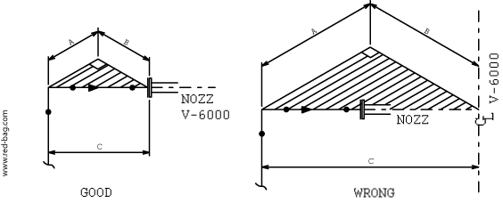
For each spool give a total dimension in every direction, dimension branches etc. from one side.
Give principal center line elevations, or face of flange elevations at equipment nozzles, the projection of the nozzle will not be given, see example above.
Give center line elevations for piping in horizontal run, try to give dimensions in the same plane as the line, e.g.:
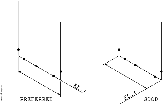
Draw flange connections, valves etc. always in the same plane as the line:


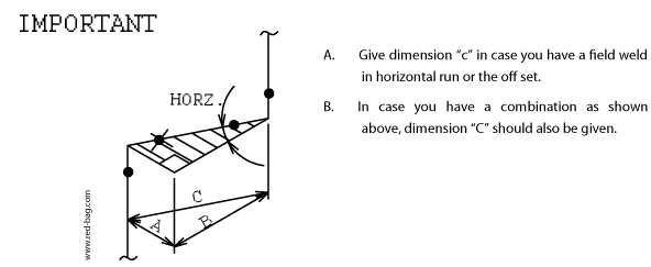
All eccentricities and off sets should be dimensioned, follow examples shown below.
Always put down whether the off set is in horizontal or vertical plane, respectively horizontal or vertical.Give angles only in cases like 30°, 45°, and 60°.
Preferably use 45° angles, an angle such as 22°-15’-41” will never be given on a pipe detail.


It is possible that you have to make an off set in two planes e.g. a horizontal and vertical off set. Below we have shown such an off set.

Typical example combination horizontal and vartical off set
Keep dimensions for spool pieces within the shipping length, limitations as shown in the specification. As these dimensions are different from project to project, it depends whether you have the pipe shop at the site or not. Approximate limitations are:
12.00 m x 2.50 m x 2.50 m
Length x Width x Height
These dimensions should always carefully be checked before using them.
For dimensioning of off set in line connected to vessel nozzle see example shown below.
Give random length pipe on long runs, but provide a piece of shop piping if you have to make a branch connection, do not dimension this piece. See example shown below:
Random length should be shown dotted. Do not dimension fw (field welds). Give overall length only.

Field welds
Stringent rules for the location of field welds cannot be given. Nevertheless, the piping designer should keep the following in mind when locating field welds on pipe details.
The number of field welds in general must be restricted to a reasonable number. This is necessary for the following reasons:
Field welds in general are made under more difficult circumstances than shop welds.
The make of any particular weld in the field in general takes about 50% more manhours than the make of same weld in the shop.
Field welds in lines requiring post weld heat-treatment cost even more.
Field welds, where necessary, are to be determined in view of the following objectives:
To limit the prefabricated spools to transportable dimensions (box dimension 12.0 x 2.5 x 2.5 meters). This also depends on the location of the pipeshop.
To limit the fabricated spools to proper handling and erection at site, the location of fw’s at high elevation should be limited to cases where else misalignment is practically unavoidable.
To provide for field adjustments in all other cases where else misalignment is practically unavoidable.
To assure tension free connections to strain sensitive equipment such as compressors, turbines and pumps. In this case, the flange has to be tagwelded in the shop. If the pipe class allows for it, use shall be made of so flanges to provide for adjustments in two (2)directions.
Provide field welds where the line is passing through a platform or fire deck. These welds should be located above the platform or the fire deck.
Field welds are to be provided at non-flexible connections between equipment and equipment or between equipment and pipework.
Field welds must be provided at such locations that rehandling of spools by heavy mobile erection-equipment will be avoided.
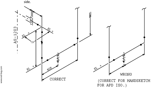
Field welds should also be provided when lines are leaving the piping area at the match line, these field welds should never be located at the match line itself, but the following rule can be used.
A. A line entering the piping area can be drawn on our isometric from the first weld in the area.
B. A line leaving the piping area can be drawn up to the first weld in the other piping area.
Special attention should be given to lines entering or leaving the pipe rack. In this cases the above mentioned rule can not always be followed. See sketch shown below.

The above mentioned rules should not be followed too stringently, because if a line has to be connected to a piece of equipment which is located near the match line the whole line can be shown on the isometric even when that sheet is numbered etc. from another piping area. Extra field welds should also be provided at piping in case a pump has his own spare etc.

Special requirements of placing field weld for particular project shall always be given by the Piping Coordinator or Squad Leader.
Instructions for the allocation of overlengths (ml)
No overlengths will be provided at the field welds connecting random pipe.
No overlengths will be provided at the field welds allocated for the purpose to stay within the box dimensions of 12.0 x 2.5 x 2.5 meters.
Overlengths will never be provided for reasons of assumed mis-installation of equipment and/or equipment tolerances. Except in cases where else misalignment is practically unavoidable.
Overlengths will be provided at field welds in piping connected to strain-sensitive equipment such as pumps, compressors, and turbines.
Overlengths may also be provided at certain field welds in high pressure (heavy wall) piping.
The latter will be studied on a case by case basis.
The Piping Group will carefully review the iso’s in the light of the above and determine which equipment piping, depending on the configuration and layout, will require these overlengths.
The overlengths will be added by hand to the apd iso.
The amount of overlength will in general be restricted to 100 mm.
The indication CTF (cut to fit) on overlengths under the dimension figure must always be added.
Isometric Projection
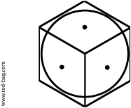
| If we consider a cube arranged in such a way that when it is viewed in plan the diagonal of this cube is in the vertical. We obtain a projected view, where all faces of the cube are equally inclined to the horizontal plans, also the three upper and the three lower (hidden) lines, meeting at the upper and lower corners, are all shortened to the same extent square root 2/3. Furthermore, if we take the three concurrent edges as axes, they are all inclined to each other at 120°. |
|
|
| Let us see what will happen if we give those axes names, such as “North”, “West” and “Vertical”, on closer inspection we could draw any arbitrary line or lines in space, parallel to our axes and also measure and scale any distance along such line or lines and whether going north, west or vertical, same distances would always scale equal amounts. | 
|
|
| This gives us a good method to represent any piping configuration, from a drawn plan and elevation, in a three dimensional way and true to any scale if so desired. | 
|

The true lengths compared to those scaled along isometric axes being in the ratio of square root 3/2 as explained by the sketch by the sketch below.

Considering now the projection of circles, if we took our cube with inscribed circles on each side and then exploded the sides we would have three isometric planes each showing an ellipse.
Thus the representation of cylinders or vessels could be done simply by extending this technique one step further.
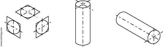
A sphere however should always retain its shape in any projection as it is three dimensional and would be inscribed inside our cube.
Piping Isometrics
Piping contains a fair amount of detail that a piping plan alone could not show.
As we have learned, isometric projection offers us a method to represent a complete pipe in space and detail and for that reason complex piping requiring shop fabrication is detailed on isometric drawings. Let us briefly consider how piping is expedited on an average project.
Small bore piping 1 1/2” and below
It is economical to assemble and route all small piping on site, using socket welded fittings pipes can be cut and welded up in the field, and final routing and arrangement of details can be left to the pipe fitter. Material for this piping is listed on “field material” sheets and shipped direct to the field stores.
Prefabricated piping 2” and larger
Larger piping using butt welded fittings is usually prefabricated in a “fabrication shop”. Isometric piping drawing are broken down into individual pipe spools and drawn up on shop fabrication spool details.
These pipe spool drawings are then used by the pipe fitters and welders in the preparation and assembly of a fabricated piping component, which on completion is then shipped to the field for final assembly.
However, as only welded items will make up a fabricated pipe spool, other components, such as valves, gaskets, bolts and other piping items, which are used in the final assembly and erection of a complete pipe only, are not needed by the fabricator, but by the pipe erector only. Therefore, this material is called “erection material” and is destined for shipment to the field.
To distinguish between these two classes of materials, shop and erection, shop fabrication items are represented by a full heavy line and erection components, valves, random lengths, etc. are drawn dotted. A piping isometric in addition to providing the necessary details for shop spools, materials, etc. Also frequently serves as an erection drawing, as it helps to identify the loose pieces of prefabricated components, by piece mark number and also shows the assembly of all piping in its right sequence.
To facilitate easier identification colour coding is used to define each piping area together with a piece mark numbering system, which relates each component to the area drawing, line number, and sequential placing.
In addition, such items as piping class, pressure and temperature, insulation, etc. are also recorded on each isometric drawing.
The attached sheets show some typical examples and suggested methods, which should be used as a guide, in the preparation and drafting of isometrics. Specific details may vary with individual job requirements and draftsmen are urged to follow the job procedures and specifications for each project.
3. Material List
Shop Fabricated Lines
On each pipe detail sheet you will find a material list which consists of two sections, the upper part has to be used for field fabrication material, and the lower part has to be used for all materials needed for shop fabrication of spool pieces.
These material lists have to be filled in by the piping draftsman as far as sizes, quantities and short description of the material are concerned.
Material control section gives the material code numbers and should make a final check on quantities used, which has to be in accordance with the material spec. BN-SP-C2.
The material control section keeps also a record of all “out of class” materials covered with a mm-numbers, same applies to mm numbers used for additional pipe fabrication details given in spec. Bn-sp-c8.
All descriptions to be used should be as possible and abbreviations given in this standard have to be used e.g.:
| Field Fabricated | Gate valve 150 lb rf flanged | |
| Material | Joint assy 150 lb | |
| Drain assy | ||
| Temperature ass | ||
| Pipe seamless c.s. sched. 40 | ||
| Shop Fabricated | Flange w.n. 300 lb rf sched. 40 | |
| Material | Flange s.o. 150 lb rf sched. 40 | |
| Conc. Red. C.s. lb sched. 40 bw | ||
| Boss s.w. 3000 lb cs |
For description of materials, use the same one as given in the material spec. BN-SP-C2.
Which materials are for shop fabrication and which are for installation in the field, is clearly distinguished on our pipe detail, because all shop fabricated materials are shown with a full heavy line and all field materials are shown dotted.
All specialities should be described as completely as possible. All necessary information needed on your pipe detail can be obtained from the material control section.
Quantities for pipe can be rounded-off up to the next 0.1 meter for carbon steel, alloy and stainless steel pipes.
Valves, fittings, assemblies etc. Should be given by the exact number needed to prepare that particular detail.
Special attention should be taken for piping materials for lines running from one area to another to avoid double ordering, the piping squad leader should make decisions on this matter.
In case of doubt when updating the material list contact the material control section.
Descriptions used can differ from one project to another, but descriptions used within one project should be the same. Field fabricated lines
Not every line in a plant will be detailed on an isometric even if the line is 2” and above in diameter and of the carbons steel pipe class, for instance pipe rack and/or pipetrack piping.
The same appears for small bore piping 1 1/2” and smaller in the carbon steel pipe class which piping will be erected in the field, the piping draftsman should make separate “Lists of Materials” for these pipe lines.
The material control section has printed forms available for both above mentioned cases.
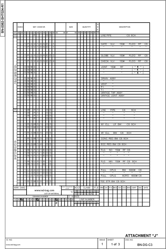
- Form BN-C21-June 1972 for 2” and above (including butt welded material)
- Form BN-C22-June 1972 for 1 1/2” and below.
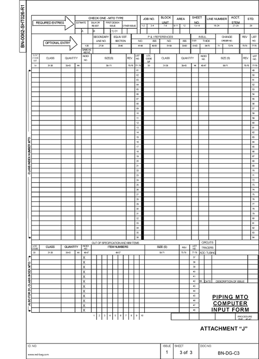
Both forms are included in this design guide as attachments. See Attachment J.
The quantities of material should be taken from the piping arrangement drawings and done as accurately as possible.
In fact the same procedure appears on these sheets as described for material lists on pipe details, the piping draftsman gives sizes, quantities only and he should finalize the preprinted description if necessary.
The material control section will finalize the material code numbers if necessary.
The form BN-C21-June 1972 should slightly be changed as follows:
A. The “S” in column 37 becomes “F”.
B. The “D” between position 15 and 16 becomes “F”.
Any deviation from pipe class material should be described, also special items such as y-type strainers, steam traps etc. According to the piping material specification.
Normal piping material descriptions can be obtained from material specification BN-SP-C2.
No pipe detail sheet or material list for field fabrication material shall be issued for construction or erection without the signature of the man in charge in the material control section.
4. Piping ISO System Drawings
Size of sheet
A. A2 format (594 x 420) sheets shall be used.
B. The use of other than A2 format shall be discussed with person in charge. Dimensions
A. Dimensions will be given in mm. No dimension less than 1 mm shall be used. Printing of notes etc. Not to be less than 5,5 mm high to obtain a readable lettering for microfilming.
B. Details like vents and drains are not required.
C. Dimensions of standard valves are not required.
D. For long runs of straight pipe, e.g. steamlines, driplegs or drains must be shown in view of possible interference with structural steel due to thermal expansion. Workspace
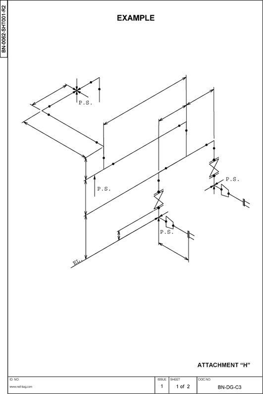
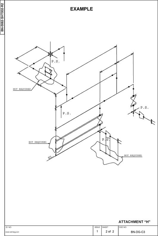
A system - drawing shall be placed on the drawings sheet the same way it appears on the piping iso (i.e. north arrow as piping iso). The north arrow shall be placed on all plans in the upper right hand corner of the sheet, using the standard north arrow sticker. See examples on Attachment H Sheet 1 and 2.
Rules for Execution of Piping Design Work for Revamp Projects
Piping Study Work at the Jobsite
The piping design work by a site design team for revamp projects will be executed according to the following general rules.
- The piping man responsible for a particular area of design takes his own field measurements as required.
- He does this all by himself as far as is practicable.
- Where he needs to be helped by one of his colleagues he requests so to the Piping Leadman.
- Any area of measurement is reported to the Piping Leadman prior to taking such measurements.
- The Piping Leadman determines which measurements/dimen-sions he wants to be “counterchecked”.
- He determines this on the basis of the criticality of the very area/spot of design.
- Criticalities are related to the following aspects:
- Risks to interference with other lines/equipment/ structures
- Large bore lines (diam. 12 inch and up)
- Special materials of construction
- Lines subject to authority approvals · Constructability of the line
- Complexity of the relevant area
- Accessibility in cases where misalignment may occur etc.
- Counterchecks are checks which are not executed by the designer who took the initial measurements.
- Counterchecks, where necessary, are at all times performed prior to making final PIPING G.A.’S and/or - ISOMETRICS.
Preparatory Work for Final Design Work at the Job Site
Prior to starting any “Final Design” work it will be decided by the project manager whether and to what extent a site survey will be performed on location/elevation of existing equipment nozzles relevant to piping revamp work.
This survey will not be executed by the piping design people, but by an outside party or by members of the construction team.
For this survey, “Equipment Instruction Sketches” will be made by the site-design team,including the survey requirements.
After completion of this survey these sketches, now indicating the proper location/elevation of the nozzles, will be used by the designers as well as by the checkers to perform their respective work.
Final Design Work at the Job Site.
The piping “Final Design” work for revamp projects will be executed as follows:
- Final piping g.a.’s and/or isometrics are, as far as practicable, prepared by the same designer who executed the piping study work for reasons of being acquainted with the relevant area. Also because final g.a.’s are in actual fact often “upgraded” piping studies.
Piping Check Work at the Job Site
After completion of the aforementioned documents, the piping leadman determines:
- By whom the area will be checked (he will at all times select a man who is qualified to do this work).
- To what extent the check will be performed.
- To which other engineering/vendor documents this will be done.
- The checker in consolation with the piping leadman, determines which field measurements he will take to support his checking activities.
Further Checks (applicable to all types of projects) After completion of the design checks, but prior to the start of fabricating the pipespools, so called “quality checks” will be performed in accordance with procedure de-qp-310 paragraph 5.3. These checks are performed by independent checkers, not directly involved in the project, assigned by the group manager piping design. General
A large portion of the site design work is dependent on:
- Practicability/reachability of existing piping components.
- Proper tools to work with.
- Experience of the people to execute the design work.
- But especially on proper and timely information on existing equipment and piping.
6. Instructions for Checking Piping Documents
Information Required by the Checker
- Check prints of final arrangement drawing
- Check prints of piping details (isometrics)
- Engineering and utility flow diagrams
- Line designation table
- Plot plan
- Equipment drawings (vessels, heat-exchangers, pumps, compressors, special equipment etc.)
- Foundations and concrete structure drawings
- Structural steel drawings
- General piping specification
- Job file (correspondence, notes etc.)
- Client’s requirements and/or bn standards
- Marked up comment prints
Checking Procedure The first step will be to make the following general check:
- Drawing number, title of drawing, issue number, date, signatures etc.
- Scale and north arrow. (see att. B sheet 1)
- General notes and drawing references
- Match lines of drawing against key plan
- Location of equipment (vessels, pumps, heat-exchangers etc.) Against plot plan.Check equipment elevations also
- Location of columns of structures and yard pipe support steel against plot plan
- Column reference numbers against structure drawings and plot plan.
The second step will be to follow through every line on the flow diagram with coloured pencil whilst marking in yellow the corresponding pipe on the arrangement drawing. Whilst doing this, check for the following items, and at the same time check the piping detail isometric:
- Direction of flow in accordance with the flow diagram
- All valves and connections correctly located
- Line numbers stated correctly, including size
- Special fittings, reducers, reducing flanges etc. Correctly labelled
- Eccentric reducers installed correctly
- Orifice flanges, control valves, level gauges, flow meters and other instruments indicated in correct position and correctly labelled
- Location of orifices so that minimum straight runs of pipe preceding and following the orifice have been obtained
- Sample points, temporary and permanent strainers, spectacle blinds, by-passes and other in-line features correctly located
- Sufficient vents, drain and traps installed in the lines where necessary, and correctly located
- Insulation and tracing.
The third step will be to make a dimensional check. (the note at the end of the first step will also apply here).
Important checking points when making the dimensional check are as follows:
- Dimensions correct, clearly shown and stated in the proper units
- Arrow heads of dimension lines drawn to the correct points
- All elevations or inverts to be from a common base line
- Elevations of bottom of pipe or center-line of pipe, nozzle, vessel or other equipment, clearly stated bop or cl as the case may be
- Elevations given to top of steel structures clearly stated tos
- Pipes at match-lines match up with ,pipes on adjacent drawings
- Check pipes at battery limits with drawing of lines entering and leaving the unit.
Whilst making the dimensional check the following items must be checked also:
- Valves suitably located for easy operation. (see bns-3208)
- Head room under pipes, platforms, structures etc. At walkways, roadways and railways
- Clearance of pipes where passing close to structures, platforms, ladders, stairways, bracing, brackets, fireproofing, handrailing etc.
- Minimum spacing between pipes (for insulated and non-insulated lines)
- Sufficient space for operating and/or maintenance at pumps, turbines, exchangers and other equipment
- Removal of internals from vessels
- Removal of screens from strainers
- Removal of tube bundles from exchangers, heaters etc.
- Removal of pistons from pumps, compressors, etc.
- Removal of internals from control valves.
Piping details (isometrics) and material lists
Isometric detail drawings will be checked at the same time as a line on the pipe arrangement drawing is being checked.
The same system of colouring will be used as for checking the flow diagram and arrangement drawings.
In addition to a dimensional check of the line the following points will also be checked:
- Drawing number, title block, notes, class, fabrication, account, reference drawing number etc.
- Material lists properly split for fabrication and erection and that all materials are identified by correct code numbers or mm numbers
- North arrow. (if required)
- Match line and/or continuation references
- Equipment numbers
- Material quantities
On completion of checking, the check prints will be reviewed by the squad leader, disputes between squad leader and checker will be referred to the piping section leader.
After correction and back-checking of the original drawings the check-prints will be filed by the squad leader for future reference.
All check prints will be sent to the piping section leader for review before filing.
Click images to enlarge: