
")
Part 4 : Earthing Installation
Table of contentsInstallation Requirements
Earthing electrodes
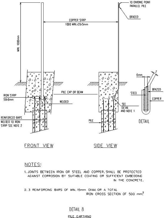
Where concrete foundation piles will be used as earthing electrode Contractor shall weld minimum 3 reinforcing bars each with a diameter of min. 15 mm or a total iron cross section of 500 sq. mm together as shown on below detail 8 as soon as pile driving and -trimming has been finished. Contractor shall measure resistance to earth of each pile used. Measuring results shall be reported to the Engineer in the usual way. (See spec. later)
The resistance of the total network to earth shall be at least below 5 ohms. Contractor shall provide sufficient (additional) earthing electrodes to obtain this.
Contractor shall determine the type and material of the earth electrodes in consultation with the Engineer. (Special consideration shall be given to possible application of “clean” earthing electrodes for instrument circuits).
In general earth electrodes shall be either:
a. An uninterrupted bare copper wire or tape with a minimum cross section of 25 sq.mm. and a thickness of minimum 2,5 mm driven into the ground by means of a steel pipe.
b. Extensible copper rods with a min. diameter of 12,5 mm (“Copperweld” or equal).
In a multiple earth electrode system the spacing of the electrodes shall not be less than the driven length.
It shall be possible to measure the resistance to earth of each individual earthing electrode, either direct or at a diving point.
Resistances of each individual earthing electrode shall be measured and test records supplied to the Engineer by the Contractor upon completion of the installation.
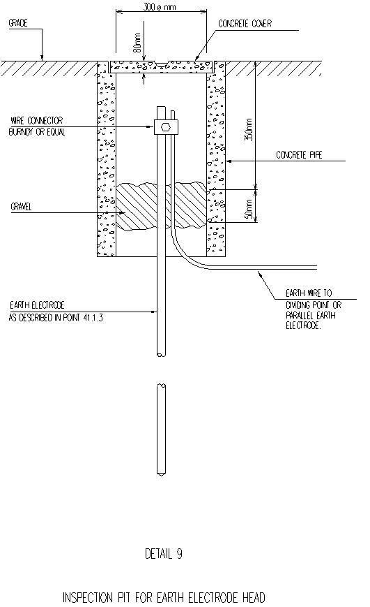
Inspection pits are required for substation and “clean” earth electrodes; see below detail 9.
Dividing Points
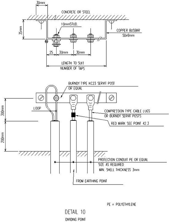
Contractor shall supply and install dividing points made of 50 x 6 mm copper and suitable to receive the necessary earthing connections. See below detail 10.They shall be located such that resistance measurements can be done in a simple way.
The main lead from an earthing electrode to a dividing point shall be marked red, at the dividing point.
Installation of Earth Wires
Above grade earthing connections not serving the lightning protection system shall be made with PVC covered copper wire, coloured green/yellow with a minimum cross-section of 10 sq.mm.Above grade earthing conductors have to run in the supporting systems made for power and lighting cabling where possible, except when they serve the lightning protection system.
Fixing of earth conductors to these supporting systems and protection of them shall be done in the same way as laid down in part I.
Joints in earthing conductors shall be as few as practicable and shall be crimped for conductors not serving lightning protection and welded or brazed for lightning protection conductors except the connection of downcomers to the underground earthing system which shall be by means of above ground installed screwed coupling.
Crimped joints in PVC covered conductors shall be insulated with PVC self-sealing tape.
Conductors used for lightning protection shall have a cross section of at least 50 sq.mm. These conductors shall be stranded and consisting of medium hard drawn bare copper wires. They shall be installed along contours such as ridges and the periphery of the roofs and shall go down (at the corners of the object) via the shortest possible way to earth.
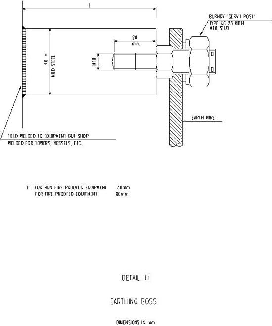
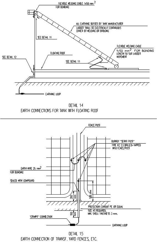
To facilitate the connection of earthing conductors to all equipment and structures the relevant manufacturers should generally provide suitable earth bosses or bolts. If, however, it should be necessary to fit such facilities in the field Contractor shall do this, at unit price, and with approval of the Engineer. (See below detail 11).
Earth wires shall be installed such that disconnection of an earthed item of equipment does not cause the disruption of the safety earthing of another item of equipment.
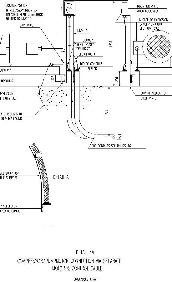
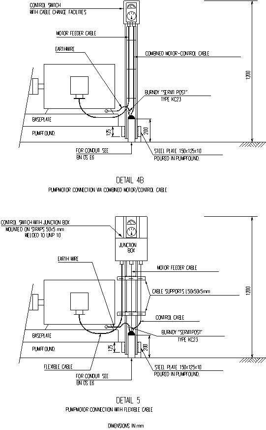
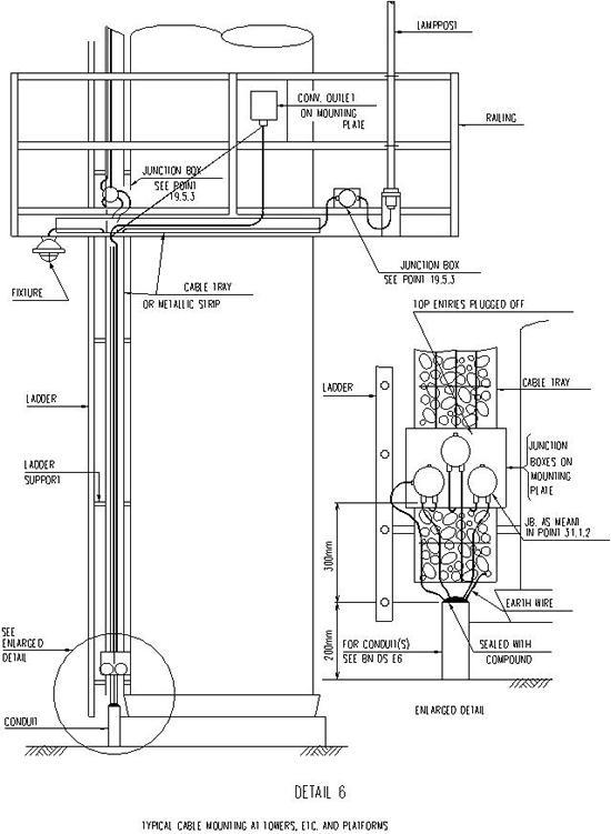
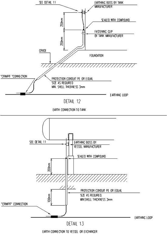
For various equipment earthing connection see below details 4 thru 6 and 12 thru 18.
Miscellaneous Requirements
Metal parts of cable trays shall be bonded and effectively connected to the common earthing grid in particular if a plastic coated finish is used.
Details incl: 4 thru 6, 8 thru 18


NOTE:
The provisions shown are minimum requirements For more extended loading racks the installation of special electronic ground indicating equipment and retracting reels is preferred. (e.g. gilbarco or securiterre)