Table of Contents
1. Purpose
Plant design models are used to optimize designs, to minimize interferences and to ensure safe operability, access and proper maintenance capability. Models are used in construction planning and can be used for operator and start-up training.
As a three-dimensional representation of the plant, models improve communications not only within Company, but also with its Clients and the authorities. Models serve as an immediate source of reference during discussions between drawing office, project, specialist, construction and maintenance engineers and safety officers.
It is most important that the Client have ready informal access to the model throughout the design stages in order that his requirements can be built into model.
2. General
Depending on the specific requirements, the model can be constructed as a block model and/or as a detailed design model.
2.1 Block Models
Block models are used in the early project stage for conceptual studies and layout in developing plot plans. They show major items of equipment, major pipe racks in a simplified form, buildings, control rooms, switch rooms and roads as well as the major piping, if relevant.
The block model is used to demonstrate that all constraints on the layout have been recognized and incorporated and that economic routing of critical and expensive piping has been considered.
Block models are low cost models, made from plastic.
2.2 Detailed Design Models
Detailed design models are used during the detailed design phase with the following main purposes and usages:
- Refinement/optimization of layouts
- As design review tool for piping configurations, piping stress analysis, electrical and instrument routing and other function al disciplines
- Safety requirements
- Equipment maintenance access
- Operational access, e.g. valving and instrumentation
- Heavy lift studies/constructability checks
- Detailed construction planning
- Operator training program
- Vizualization of modular/PAU construction and dressed towers
- Definition of revamp models between existing/new/revamp equipment and piping
The check list included in Attachment 1 shows the typical use of the model by Company, its Clients and others in relation to the development of the piping design documents.
Detailed design models give an accurate detailed layout of piping and utilities and control facilities. The extent of modelling is described in section 4.1.
Detailed design models are attached to model tables of manageable size.
The model is located within the Piping Design Group and available for continuous review by all parties.
3. Responsibilities
The Project Manager or his delegate is responsible to identify the model requirements and to plan and execute regular model reviews on the piping model.
The Piping Squad Leaders have the responsibility to ensure that Piping Design Model Makers assigned to their squad are using this procedure and the latest design information/instructions.
Piping design employees/Model Makers preparing the model have the responsibility to closely follow this procedure.
The Model Maker is jointly responsible with the Piping Squad Leader for the quality of the model. The fact that the model is checked does not relieve the Model Maker of his responsibility.
Responsibility for the design stays with the Piping Design Group. In case of doubt or error, the Model Maker has to refer back to the Piping Squad Leader.
4. Procedure
4.1 Model Requirements
The Project Manager shall ensure that the model requirements for the project are defined and he shall obtain approval from the Client if required.
To prepare a model estimate the Guide, ref. 6.10, may be used.
When defining model requirements, the following shall be considered:
4.1.1 Types of Basic Models
- Simple block model for plot studies which will not be fully piped up
- Full scale basic model which will be piped up to be used for piping layout
4.1.2 Types of Piping Model Systems
- Center line system
- Partly center line and full scale system
- Full scale plastic piping system
4.1.3 Model Scale
Piping design models are built to scale 1:33-1/3. For special cases scales 1:25 or 1:16 can be used. Block models are built to scale 1:100 or 1:250.
4.1.4 The Areas or Units to be Modelled
The preparation of models for areas where only a few pieces equipment are located shall be minimized. Duplicating hook ups shall be shown only once in full detail.
4.1.5 Extent of Items to be Modelled
- The detail of the model to be prepared shall be as described in the guide for the preparation of design models, ref. 6.4.
- Special project/construction/Client requirements shall be included during the preparation of the model.
- Information concerning above model requirements for a specific project shall be sent to the Piping Squad Leader with a copy to the Manager Engineering.
4.1.6 Subcontracting Model Work
The extent of subcontracting model work for the project shall be defined. Subcontracting of model work is further described in the procedure for procurement of design models, ref. 6.3.
4.1.7 Model Reviews
The Project Manager shall agree with the Client the percentage completion(s) of the model for the required model reviews. It is Company's normal practice to have formal model reviews at 30%, 60%, 90% and 100% completion of the model. See also section 4.5
4.2 Model Planning
The Design Coordinator shall, in consultation with the Piping Squad Leader, prepare a level IV of planning schedule, ref. 6.2.
The Piping Squad Leader shall prepare a manpower planning.
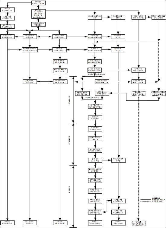
Attachment 2, the production flowchart of piping design documents could be used when preparing the planning schedule.
4.3 Preparation
The scope of the block/detailed design model(s) is defined in section 4.1.
The plant design model is built according to piping, civil, structural, instrument, electrical and vessel drawings, vendor drawings for equipment and input on constructability from the Construction Department. The model shall be used as a design tool.
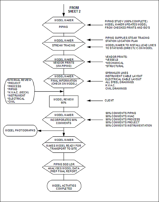
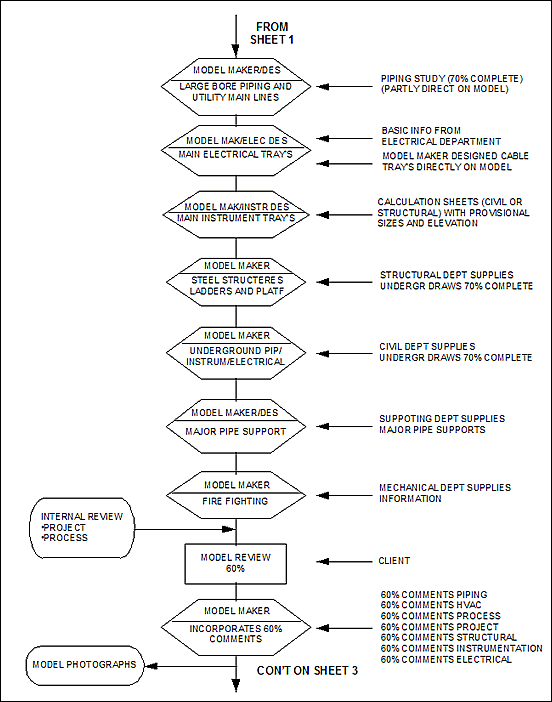
Attachment 3, the production flowchart "Preparation of the Design Model", details the major steps required for design model fabrication.
To construct the model tables, a model table layout shall be pre pared.
To fulfill the requirements of health and safety at work, personnel working in the model shop are required to adhere to the procedure "health and safety requirements for model shop", ref. 6.8.
See the procedure for development of detailed design models, ref. 6.3.
See also the guide for preparation of design models, ref. 6.4.
4.4 Checking
Before a formal model review is executed, the model must be rigorously internally checked for compliance with all design criteria.
The design guide, ref. 6.6, shall be used for checking the model.
The model review procedure ref. 6.1 may also be used to follow all required steps to check the model internally.
4.5 Model Review
The model review(s) shall be executed in accordance with ref. 6.1 and ref. 6.5 on the defined stages of percentage completion of the model. The guide for checking the design model, ref. 6.6, shall be used during the model review.
4.6 Photographs of Piping Model
During construction of the model, color photographs shall be taken immediate after incorporation of the comments of the (30-60 and 100%) model review, if requested by the Client. See ref. 6.7.
Upon completion, the model shall if requested by the Client, be photographed from various angels. Close-ups photographs shall be made if more detailing of equipment, piping, etc. is required.
The assumed location from which each photograph has been taken shall be indicated by arrows on a plotplan drawing. Each photograph will be indicated with a project number and date.
4.7 Packaging and Shipping
The completed model shall be packed and shipped in such a way as to withstand damage during transport to its destination (see ref. 6.9).
This work shall be done by a specialist full experienced in this type of work.
All crates shall be properly marked with regard to content fragility and position. Quotation for packing and shipping will be handled by the Traffic Coordinator.
4.8 Model Data Analysis
If it is required to analyze the model data after the completion of the model, see guide ref. 6.11.
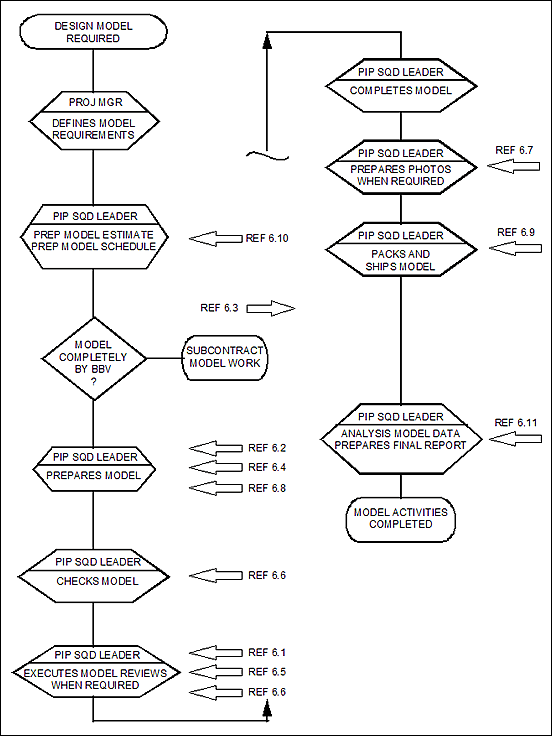
5. Flowchart
6. References
| Document Number | Title | Level | |
| 6.1 | CM-PE-506 | Model Review | 2 |
| 6.2 | CM-PE-508 | Development of Detailed Design Models | 2 |
| 6.3 | BN-EP-306 | Procurement of Design Models | 3 |
| 6.4 | BN-DG-C4 | Design Guide for Preparation of Design Models | 4 |
| 6.5 | BN-DG-C5 | Design Guide for Conducting Model Reviews | 4 |
| 6.6 | BN-DG-C6 |
Design Guide for Checking of Design Modelsand Definition of Percentage Completion |
4 |
| 6.7 | BN-DG-C7 | Design Guide for Model Photographs | 4 |
| 6.8 | BN-DG-C8 | Design Guide for Health and Safety Requirements for Model Shop | 4 |
| 6.9 | BN-DG-C9 | Design Guide for Packing and Shipping of Design Models | 4 |
| 6.10 | BN-DG-C10 | Design Guide for Model Estimating and Cost Control | 4 |
| 6.11 | BN-DG-C11 | Design Model Final Data | 4 |
7. Attachments
1. Usage of Detailed Design Model
2. Production Flowchart of Piping Design Documents
3. Production Flowchart Preparation Design Model
Attachment 1
USAGE OF DETAILED DESIGN MODEL
During Design
Listed below are the various applications for which the model is used by Company and when.
|
When |
By Whom |
Application |
|
During design phase (Model approximately 30% complete) |
Process Engineer |
Review of operability. Review physical configurations of large bore critical process lines and location of all major equipment to ensure that process requirements are met |
|
Project Construction Coordinator |
Coordinating with and providing advice to project and design engineers in the development of the plotplan and constructability of design |
|
|
During design phase |
Project Engineers |
Check if all client's requirements are met |
|
Early design phase equipment |
Above Ground Piping Section |
Check layout of equipment |
|
During design phase |
Above Ground Piping Section |
Check layout of piping (e.g. Consistent hook-ups) |
|
Early design phase |
Pipe Supports/ Stress Section |
Study critical process piping |
|
During design phase |
Pipe Supports/ Stress Section |
Check anchor points and supports location |
|
During design phase and early design phase |
Pipe Engineering Section |
Check critical piping to improve layout or (if required) possibilities for changes |
|
During design phase |
Vessel Design Section |
Check nozzle orientation |
|
During design phase |
Vessel Engineer |
Check on calculations for wind loadings. Solve expansion problems |
|
During design phase (model approximately complete) |
Process Engineer |
Check on completeness. Review of operability 50%. Review physical configurations and location of all equipment to ensure that process requirements are met. Review hydraulics (pump lines and NPSH requirements), safety valve, inlet and outlet lines, flare and blow down lines |
|
During design phase |
Instrument Design Section |
Check on location of instruments, orifices, analyzer connections, cable trays, etc. Check on accessibility of instruments |
|
During design phase |
Underground Piping Section/ Fire Fighting Engineer |
Check location of utility stations, fire hydrants, monitors, drain cups and catch basins |
| During design phase | Electrical Design Section | Check on above ground cable layout, cable trenches, lighting, lighting panels and welding outlets location. |
| During design phase | Structural Design Section | Check for ladders, platforms, drop-out areas, hoisting and trolley problems, interference of portal frames and bracing |
| During design phase | Piping Design Section Heating and Ventilation Engineer | Check of ducting, layout of heating, ventilation and air-conditioning in buildings as applicable |
| During design phase | Construction Department | Check on clearances for construction equipment and develop craneage plan. Act as visual aid for scheduling and planning. Improve definition of scope of work for subcontracting. Check economic loop testing. Minimize the use of scaffolds. |
During Construction
After completion, the model is shipped to the site, where it is used, among other things, for detailed construction planning.
BY CLIENT
Listed below are the various applications for which the client may use the model:
- Regular reviews at formal model review sessions. Engineers from both client and contractor participate
- Review more rapidly a three-dimensional portrayal of a particular design or design change
- Evaluate progress made during the critical design phase
- Participate more directly in discussions about engineering and design philosophy, aesthetics and design preferences
- Review and approve drawings more rapidly, which will be advantageous for design progress
- Review maintenance requirements and planning, without intensive study of the relevant drawings
- Review safety and accident combatting requirements (such as location of monitors, etc.)
- Use the model for training of operational and fire brigade personnel and in start-up operations, particularly to indicate the sequence of equipment and piping operations. Language difficulties will be reduced with this visual aid
- (Senior) management need not review design drawings to visualize the new project
- Operators can review the operability of the plant
BY OTHERS
Authorities adjudicating interpretation of local and general design codes may use the model, as well as insurance brokers.
Attachment 2
PRODUCTION FLOW-CHARTPIPING DESIGN DOCUMENTS USING APD-ISO
PRODUCTION FLOW-CHARTPREPARATION DESIGN MODEL
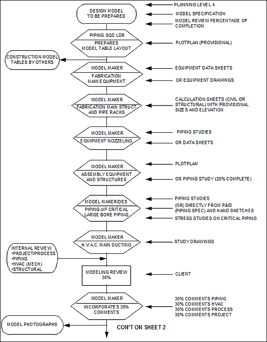
Attachment 3
PRODUCTION FLOW-CHARTPREPARATION DESIGN MODEL (CON’T)
Attachment 3
PRODUCTION FLOW-CHARTPREPARATION DESIGN MODEL (CON’T)
