
")
Table of Contents
1. Purpose
Define the necessary steps to be followed in the preparation of engineering flow diagrams (EFD's).
Define the necessary steps to be followed in the preparation of documents related to the EFD’s, i.e.: demolition diagrams, line tables, list of revision sheets, tie-in index, miscellaneous material lists (MM).
2. General
The EFD’s and related documents establish the plant configuration and are the key documents for the development of piping and instrumentation construction drawings.
The EFD’s are the most widely used documents during the engineering, procurement, construction, and startup phases of a project. Timely, complete, and high quality development of these documents enhances execution of the overall project.
3. Responsibilities
Depending on project scope and size certain positions described in the following sections may be combined or eliminated. The functions, however, remain as valid execution requirements which must be assigned within the established project organization. The independence of QC and QA activities must be maintained when making such reassignments.
3.1 Process Engineering Responsibilities
3.1.1 Process Supervisor
a. The Process Supervisor has the overall responsibility for the Systems Engineering scope of work.
b. The Process Supervisor has the responsibility for all process engineering inputs to the EFD’s and related documents.
c. The Process Supervisor is responsible for Process Engineering's quality control of the EFD’s and related documents and assures the documents are technically correct, meet the intent of the process design, and reflect all facilities for startup, shutdown, and performance verification. The Process Supervisor shall approve all the issues of the EFD’s, Demolition Diagrams and Line Tables (see ref. 6.4).
d. The Process Supervisor, in conjunction with the Plant Commissioning Engineer, ensures the EFD’s contain adequate provisions for startup and decommissioning. He reviews all EFD’s and adds/revises piping, as required, to allow safe operation, safe and efficient startup, shutdown, and decommissioning. Additional or revised instrumentation, where deemed required, shall be discussed with the Control Systems Engineer prior to incorporation into the EFD’s. This review will be completed on the "For Client Comments" or "For Approval" issue of the EFD’s.
3.1.2 Unit Process Engineer
The Unit Process Engineers on a project are assigned sections (units) of a plant for which there is an associated block of EFD’s. The Unit Process Engineer’s EFD and related document responsibilities are as follows:
a. Defines process details, such as required elevations, two-phase flow definition, gravity flow, startup and shutdown requirements, performance verification requirements, tracing, location of control valves (grade or at equipment nozzles), sample connections, etc.
b. Defines the system control philosophy. Part of this activity is the basic definition of required process instrumentation to monitor/verify that the system is operating correctly and the verification of the detailed definition by the Control Systems Engineer on the EFD’s.
c. Defines the required safety devices (relief valves and rupture discs). Defines how emergency shutdown (ESD) systems function, i.e., preparation of ESD matrices, in close cooperation with the Control Systems Engineer and the Process Control Engineer.
d. In conjunction with the preparation of the line table, establishes line sizes, operating pressures and temperatures, design pressures and temperatures, maximum temperature for thermal stress, and process insulation and tracing requirements. Gives input for class selection such as toxicity, corrosion and material.
e. Defines decommissioning/pumpout requirements.
f. Defines the number, type, and location of sample points.
g. Defines the process specifications (as required) for MM items.
h. Establishes pickling/chemical cleaning details for the plant.
3.2 Systems Engineering Responsibilities
3.2.1 Systems Engineering Coordinator
The Systems Engineering Coordinator is responsible for coordinating the overall engineering flow diagram effort on a project. All Systems Engineers will receive technical direction and assistance from the Coordinator. The Coordinator reports to the Process Supervisor. For larger projects it could be considered that the Coordinator directly reports to the Project Manager. Depending on type and size of the project one or more Lead Systems Engineers may be assigned taking over certain tasks and responsibilities of the Coordinator.
On each project a Systems Engineering Coordinator shall be nominated in cooperation with the project Manager and the Manager Systems Engineering. On smaller projects where the function of Engineering Coordinator is not a full time job, this function shall be combined in one person for several projects. In the latter case the responsibility for meeting the objectives of the budgets and the established project schedule will reside with the Process Supervisor (see item b).
The Systems Engineering Coordinator has the following responsibilities:
a. If required, prepares a project specific design guide for the preparation of flow diagrams using standard design guide ref. 6.9. Ensures the EFD’s comply with this design guide.
b. Works with the Engineering Manager, the Process Supervisor, the Project Control Manager, and the Lead Project Engineer(s) initially to establish the EFD schedules, manpower loading and budgets and is responsible for meeting the objectives of the established project schedule.
c. Provides technical direction and assistance to the Systems Engineers. Ensures consistency of design and display of details.
d. Assist Systems Engineers to ensure EFD inputs are properly interpreted, resolved, and incorporated.\
e. Regularly audit diagrams with respect to compliance to procedures, standards and work methods.
f. Reviews maintenance of “master” flow diagrams.
g. Identify the need for training and report to the Manager Systems Engineering on training requirements of personnel.
h. Issue timely reports to the Project Manager, the Process Supervisor, the Systems Engineering Manager and the Department Manager Process Engineering, so that corrective actions can be taken.
3.2.2 Systems Engineer
The Systems Engineer is assigned with a block of EFD’s, with complete execution responsibility, as is defined below. The Systems Engineer reports to the Lead Systems Engineer or, in his absence, directly to the Process Supervisor.
a. Ensures the EFD formats and content comply with the project specific design guide for the preparation of engineering flow diagrams.
b. Ensures all EFD inputs provided by others are correctly incorporated and depicted. Prior to incorporating the inputs, the Systems Engineer technically understands, or is convinced of the reliability of the given input, ensures consistency of inputs, and ensures conformance with standard project details.
c. Ensures that requests for revision to "Certified" EFD’s are within the scope of work, required for safety, operability, or authorized by a change order.
d. Performs equipment checks, by using equipment specifications and vendor drawings, to ensure that equipment details shown on EFD’s are accurate. Ensures the correct interface between equipment and instrumentation as shown on the EFD. Ensures consistency between equipment nozzles and the piping/instrumentation sizes, ratings shown on the EFD’s.
e. In conjunction with the preparation of the line table, numbers lines, completes fluid from/to, selects line classes, and specifies test pressures and mediums.
f. In conjunction with the preparation of the line table, specifies insulation and tracing requirements for mechanical reasons i.e. winterizing and personnel protection and specifies insulation thickness for heat conservation.
g. Selects valve types, using the Specification for Piping Material as the basis.
h. Selects block valve sizes for pump and control valve manifolds.
i. Works with Control Systems Engineering to ensure that the EFD’s are consistent with the Control Systems design documents.
j. Prepares and issues flowsheet revision sheets or prepares list of revisions sheets.
k. Prepares list of MM- items.
l. Prepares the tie-in index.
3.3 Control Systems Responsibilities
3.3.1 Control Systems Engineer
The Control System Engineer defines the instrumentation, based on basic requirements as shown on the Process Flow Diagram (PFD) and assures that all required instrumentation is included and correctly indicated on the EFD’s, and uses the process instrument data, to size the control valves, relief valves, and other in-line instruments.
3.4 Mechanical Engineering Responsibilities
3.4.1 Equipment Specialist Engineers
The Systems Engineer consults the Equipment Engineers for P, G, and H account equipment to ensure the equipment details shown on the EFD’s are correct and agree with equipment specifications and vendor drawings.
3.4.2 Insulation/Painting Engineer
The Insulation/Painting Engineer specifies insulation and paint requirements in specifications for insulation and painting. The Systems Engineer is to apply these requirements when completing the relevant columns in the line table.
3.4.3 Acoustical Engineer
The Acoustical Engineer consults with Process Engineering and Specialist Engineers concerning items generating excessive noise. Having determined the appropriate course of action, the Acoustical Engineer advises the Systems Engineer of any required revisions to the EFD’s.
3.5 Piping Design Responsibilities
3.5.1 Design Squad Leader
The Piping Design Squad Leader oversees and supervises all piping design generated EFD’s comments and inputs. The Piping Designer is responsible for notifying the squad leader when EFD revisions are required as a result of detailed piping layout or revised routing. The Squad Leader advises the Systems Engineer of changes.
3.6 Project Engineering Department Responsibilities
3.6.1 Project Engineering Manager
The task force Project Engineering Manager's function in this area is primarily administrative. The Project Engineering Manager coordinates the preparation, development, and issuance of EFD’s and related documents with all involved engineering departments and the client. He also is responsible for implementation of the quality assurance program for the diagrams and related documents.
3.7 Departmental Split of Work
A typical matrix is listed in Attachment 1. This matrix shows the major tasks associated with the preparation of EFD’s and related documents, with a listing of the functional disciplines having the prime responsibility for each task.
4 Procedure
4.1 Presentation
4.1.1 Format
For forms, index sheet and page numbering requirements refer to procedures (ref. 6.4). For the formats to be used refer to procedures (ref. 6.7).
4.1.2 Numbering
Document numbering for the project shall be defined in the project procedure and execution manual.
Refer to procedures (ref 6.2, 6.4 and 6.5).
4.2 Production
4.2.1 Procedure for Engineering Flow Diagrams (EFD's)
4.2.1.1 Introduction
a. The EFD’s are most widely used of all engineering documents during the engineering, design, and construction phases of a project, with heavy use continuing during the field checkout and startup phases. The EFD’s display the inter-relationship of the equipment, piping, and controls to provide efficient and safe operation. They are the prime documents used for development of the piping and instrumentation construction drawings. They serve also as valuable reference documents and operator training tools for the client. The EFD’s are given by:
- Client
- Process Engineers and Plant Commissioning Engineers
- Mechanical Engineers (rotating equipment, general equipment, fired heaters)
- Electrical, Control Systems, Piping, Insulation, and Acoustical Engineers
- Piping Design Group
Given the many sources of input during an extended period, it is apparent the EFD’s are documents which develop continually during the entire engineering and design effort. The EFD’s are not final until the plant is constructed, and "as-built" modifications (if required) are incorporated. It is imperative that the EFD issues reflect the best current information available.
b. Some clients wish to refer to the EFD’s depicting facilities and equipment used to provide utility services, i.e., cooling water, steam, boiler feed water, demineralized water, air, etc., as Utility Flow Diagrams. For the purpose of this procedure, they are to be considered as EFD’s.
c. Utility distribution diagrams (UDD's) are the engineering flow diagrams that show the layout of the utility services headers and subheaders and the branches to consumers. They are arranged in a geographic format. Utility services for which UDD’s normally are prepared include steam and condensate (all pressure levels), hot oil, plant and instrument air, nitrogen, water (supply and return cooling water, potable, raw, plant, demineralized, etc.), brine, fuel gas and oil, flare systems, and various flush mediums for pump seals and instruments.
4.2.1.2 Titles and Criteria for Engineering Flow Diagram Major Issues
a. For Internal Comments
For this issue the Systems Engineer has pieced together as much process flow diagram, equipment and EFD format information as is available at the time, in order to issue a diagram for various groups to mark-up and review.
b. For (Client) Comments/Approval
By this issue, the envisioned plant has been defined by various input groups. The client (if required) and the input groups are requested to comment on a fairly complete set of EFD’s prior to commencement of final detailed engineering and design. At this point, many details such as sizes of in-line instruments, relief valves and pumps are not known and subjects such as miscellaneous pump piping and piping MM items are not yet defined. This issue, however, contains the basic plant configuration and line sizes, pipe classes, instrument numbers, insulation and tracing requirements, valve tag numbers, and startup and decommissioning provisions.
This issue authorizes piping design to begin piping studies.
c. Approved/Certified for Detailed Design
This issue resolves and incorporates the client (if required) and the input group's comments. It contains the control valve sizes, relief valve sizes, other in-line instrument sizes, pump nozzle sizes, pump valve sizes, control valve manifold valve sizes, and sample and chemical cleaning connections.
For in-house designed equipment (A, M, TT, etc.), the latest available revision of drawings and specifications is incorporated.
For vendor designed equipment, the information from the latest revision of specification and vendor drawings is incorporated.
For vendor designed equipment, where the major equipment documents affecting the piping design are available but complete auxiliary system documents are not available, the information from the "Certified" specification on the major equipment details is incorporated. EFD’s for the auxiliary systems would be certified after incorporation of information from the vendor prints.
The "Certified for Detailed Design" issue authorizes the design groups to begin final design drawings.
Any details that cannot be finalized at this stage due to a lack of information from vendors, other disciplines, etc, should be clearly marked as "HOLD". Holds shall be restricted to the absolute minimum for this issue.
d. As Designed (Optional)
For this issue, the EFD is updated to reflect the plant as it was finally designed and engineered in the home office.
e. As-Built (Optional)
For this issue, any field changes are incorporated on the EFD for record purposes. This issue would be made only if it is a job requirement.
f. A typical matrix is listed in Attachment 2. This matrix form shows the EFD technical content for major issues reflecting the information that should be incorporated onto the major flow diagram issues.
Note that there will be additional issues of the engineering flow diagrams to keep functional groups up-to-date with the latest information. These issues shall be titled "Updated/Revised as Marked".
All issues should be identified, this includes internal issues to a limited group of people for a particular purpose. This purpose shall be noted in the internal issue (ref. 6.3).
4.2.1.3 Procedure
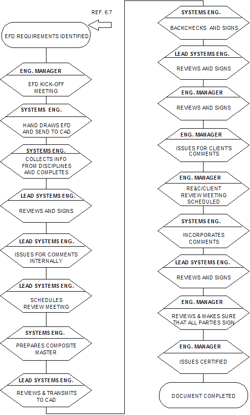
The procedure for preparation of EFD’s is detailed below. A flowchart for EFD preparation is attached in 5.1. This depicts the procedure for a Company standard project.
Signing and approval
Signing and approval of EFD’s will be in accordance with ref. 6.4.
EFD kick-off
Engineering Manager calls an EFD kick-off meeting to be attended by the Process Supervisor, the Lead Systems Engineer (LSE), the Systems Engineers (SE), the Unit Process Engineers (UPE), the Control Systems Engineer (CSE), the Project Control Manager, and the Engineering/Design Coordinator. The purpose of this meeting is to discuss specific client and job EFD requirements, standard details and instrumentation requirements/formats, schedules, required level of detail on the EFD's (consistent with contractual requirements), requirement for equipment EFD’s (e.g., for compressors, etc.), requirements and extent of UDD's. If the job-specific EFD guide (ref 6.7) has yet to be issued at this time, it should be issued as soon as possible and the same applies to the project EFD legend and symbols sheet.
Issue for internal comments
Using the PFD's, the job specific EFD guide (ref 6.7) and any appropriate EFD's from past jobs (taking due note of different process conditions, Client requirements, instrumentation systems and format differences) the Systems Engineer (SE) hand draws the outline of the EFD's showing equipment outlines and major lines and valves only and transmits them to the CAD.
The SE continues to develop the EFD's including completion of all lines, incorporating equipment details (from the equipment data sheets), completion of the instrumentation, incorporation of all secondary lines, and relief valve requirements.
The SE consults with the UPE and the CSE on a case-by-case basis to ensure that all technical job requirements are properly represented on the EFD's. He also consults all pertinent job specifications including basic design data , C-1, C-2, K-1 pertinent equipment general specifications, ISA-S5.3 (for jobs with distributed control systems), and client specification and design requirements, process data sheets, available equipment data sheets, project bulletins, and the project legend and symbols sheet.
The SE develops the line table (with line number, fluid description, and to and from columns completed), requesting incorporation of the line sizes, operating and design conditions, and the (generic) piping materials by the UPE.
After receiving the line sizes and materials from the UPE, the SE incorporates the line sizes on the EFD's and line tables and completes the line classes. The job-specific C-1 specification (or client imposed equivalent) should have been issued at this time. The SE transmits the EFD's and corresponding line table to the LSE for review and issue.
The LSE reviews the diagrams and line table (QC), signs them and transmits them to the Project Engineering Aide for Issue "For Internal Comments." The corresponding line table is also issued at this time.
In conjunction with this issue, the LSE writes a memo to the Process Supervisor, the UPE, the Start-up Engineer (if required), the CSE, the appropriate Equipment Engineers as required, the Engineering/Design Coordinator, and the Engineering Manager requesting comments on this issue of the EFD's and setting a date for an internal review meeting. A copy of the memo is sent to the SEC.
Internal review meeting
An internal EFD review meeting is held, attended by the LSE, the SE, CSE, the Start-up Engineer (if required), the appropriate Equipment Engineers, and the UPE (mandatory), the Engineering/Design Coordinator (optional, but strongly recommended), and the Process Supervisor and Engineering Manager (optional). The purpose of this meeting is to collect all input into the EFD's, comments and new information, and to discuss the EFD's in detail. Comments are agreed upon and marked on a copy of the EFD's. Prints of these copies are transmitted as attachment to the MOM to all attendees immediately after the meeting.
Issue for Client comments
The SE prepares a composite EFD master, incorporating all decisions and comments of the review meeting. The EFD masters are transmitted to control systems for instruments numbering (if not already included) and returned to the SE, who transmits this master to the LSE. The LSE reviews the EFD masters (QC) and transmits them to CAD to be drafted.
CAD updates and back-checks the EFD's and transmits them to the appropriate SE. The SE back-checks the EFD's, recycles them to the CAD for corrections and after they are acceptable, he signs them and transmits them to the LSE.
A copy is sent to the SEC for review (QA). Comments are discussed with the SE, LSE, SEC, reported to the Project Manager and incorporated by the CAD. (Note: The review by the SEC may be done in parallel with obtaining client comments).
The LSE reviews the EFD's, signs them (QC) and transmits them to the Engineering Manager for signature. The EM signs them (QA) and transmits them to the Project Engineering Aide for issue, "For Clients Comments." The corresponding line table should also be issued at this time, complete with line sizes and line classes.
In conjunction with this issue of the EFD's, the Engineering Manager establishes the time and place for a review meeting. Requested to attend this meeting are the Process Supervisor, Unit Process Engineer, Control Systems Engineer, LSE, individual Systems Engineer, and the client (if required).
EFD Clients review meeting
An EFD client review meeting is held. Client comments are discussed and then marked on copies of the current EFD's. In addition, Company highlights and discusses any revisions that have developed since the last issue of the EFD's. Prints of all comments are transmitted to the client and all meeting attendees immediately after the meeting. Minutes of meeting are prepared by the SE and signed by the PS, EM, and the client. It is recommended to write the MOM during the meeting.
The SE incorporates the client comments in close cooperation with all input groups onto the EFD master (utilizing the CAD if required) and transmits them to the LSE for his review. The SE also updates the line table and transmits to the LSE as well. The LSE confirms that all comments are correctly added to the EFD's and transmits them to the Engineering Manager. As part of the preparation of "Certified" issue, the Engineering Manager may need to call a review meeting to resolve any outstanding questions.
The certified issue of the EFD's is signed by all personnel, of whom a signature is required as established in ref. 6.4. The signatures denote that signees are in agreement with and approve their areas of responsibility as defined in section 3.0. The certifying authority is the Project Manager, who signs the "Certified" line on the title block (QA). The client's signature may or may not be required for this issue.
Finally, the Engineering Manager transmits the signed EFD's originals to the Project Engineering Aide for issue as "Certified."
Post-certification EFD issues will be made as needed, and will be based on comments generated by the UPE, Piping Design Coordinator, CSE, Start-up, Equipment Engineers, LSE, Electrical Engineer, and the SE. It is the responsibility of the SE to ensure that their comments are correctly interpreted and shown on EFD's. All of these subsequent EFD issues must be signed by the individual Systems Engineer, LSE (QC) and may require the signature of the Engineering Manager ( ref. 6.4). Corresponding EFD revision sheets and line table revisions must accompany each issue.
Notes:
(1) After each EFD issue, the ‘void’ project master mark-ups are filed, and a new master is started using the new issue.
All CAD check prints containing additional EFD input shall be filed together with the void masters.
(2) All issues should be identified, this includes internal issues to limited group of people for a particular purpose. The purpose of this issue shall be noted on the internal issue. See ref. 6.3.
4.2.2 Preparation of Demolition Diagrams
4.2.2.1 Introduction
Demolition diagrams highlight all equipment, piping and instruments that have to be demolished.
They form part of the construction package and are used for the mechanical subcontract to determine the exact scope of demolition work as the basis for the bid package. The drawings are also used fore the same purpose by the Company disciplines throughout the design phase.
4.2.2.2 Procedure
The Systems Engineer is responsible for identifying on the drawings the equipment, lines and instrumentation which are no longer required and coordinates the input from other disciplines. The various engineering departments are responsible for defining the most practical extent of the demolition scope. A close liaison between the Systems Engineer and the Piping Engineer is required at the start of the project to interpret the basic data to the correct extent of demolition.
Demolition diagrams shall always be issued together with the project EFD's.
In the title block the flowsheet description e.g. "Engineering Flow Diagram" shall be replaced by "Demolition Diagram".
The drawing lead number to be used is 138. The subletter to be added shall be the same as for the project EFD. E.g. drawing XXXX-138A is the demolition diagram, corresponding to the project EFD drawing XXXX-107A.
Existing revision descriptions shall be deleted.
In the notes column a hatched cloud shall be added with the note "Denotes Equipment to be Modified/Removed for Project XXXX.XX.XX".
Equipment, Piping, Instruments to be demolished shall be clouded and hatched, inclusive the equipment tabulation.
For systems to be relocated/reused an information note shall be added next to the cloud.
Tie-outs shall be numbered and listed
4.2.3 Preparation of the Line Table
4.2.3.1 Introduction
The line table is a listing of pipelines appearing on the EFD's. It contains information of the fluid, operating pressure and temperature, design pressure and temperature, insulation code and thickness, paint code, and type of heat tracing. Additionally, information on test pressure and test medium may be required, as well as other information related to authority requirements, such as boiling point, hazard category, etc. The line table is an important adjunct to the EFD's and also is the basis for piping stress analysis, piping system testing, and the piping portion of the painting and insulation subcontract.
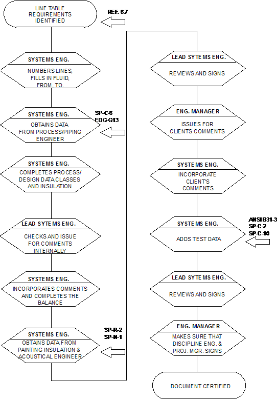
4.2.3.2 Procedure
The procedure for the preparation of the line table is detailed below. A flowchart for line table preparation is attached in 5.2. This depicts the procedure for a Company standard project.
A job specific guide (ref. 6.9) defining format and work systems will be prepared by the SE Coordinator.
A Systems Engineer fills out the overall line table cover sheet including definition of line number blocks, process fluid abbreviations, and standard notes.
The Systems Engineer numbers lines and fills out all line table columns using the PFD's as a basis, marked-up with Material/Pipe classes, Design Pressures and Temperatures by the UPE (the P-T diagram), and insulation/tracing information.
The Process Supervisor reviews the process line table mark-up and indicates the critical lines to be checked before the final piping design is completed. The marked-up line table is transmitted to the LSE for incorporation into the line table original by the SE. The LSE checks and issues the line table "For Internal Comments" with the corresponding issue of the EFD's.
The list of critical lines is issued to the Engineering Manager. The Engineering Manager ensures that the piping design is checked before being finalized by the Unit Process Engineer. The Process Supervisor signs off on the list of critical lines for those lines checked and approved by the Unit Process Engineer. The Engineering Manager, notified by the Process Supervisor, arranges for the final piping design of the approved critical lines.
The LSE requests comments from the UPE, the Engineering Design Coordinator, and the Piping Design Engineer.
The Systems Engineer incorporates inputs from the process and piping design line table masters onto the line table originals. He also fills out the balance of the insulation codes (PP, AS, etc.), and the maximum temperature for thermal stress. This last column is done in consultation with the UPE and Pipe Stress Engineer.
The Systems Engineer consults the Painting/ Insulation/Acoustical Engineer and applies their requirements when completing the relevant columns. He also consults with the CSE to determine if any control valves require insulation for noise.
The Systems Engineer transfers comments from the project master and incorporate into the line table originals. The SE assembles the line table sheets with its cover sheet. The LSE reviews the line table originals, signs it (QC), and transmits it to the Engineering Manager. The Engineering Manager signs it (QA) and has it issued with the corresponding EFD issue as "For Clients Comments" or "For Approval" as applicable.
a. The Engineering Manager interfaces with the client to obtain line table comments. These are transmitted to the LSE who in turn has them noted on a master copy by the SE, who checks and incorporates client's comments consulting with any specialists involved, if required.
b. Company comments are again requested. These are transmitted to the LSE by means of the master mark-ups from process and piping design.
The Systems Engineer incorporates both internal and client comments into the line table original.
The Systems Engineer also fills out columns: Testing Medium and Testing Pressure (using XXXX-SP-C-10 as basis), and Service Classification using (XXXX-SP-C-1 and C-2 and ANSI B31.3). He consults the Piping Engineer and the UPE as required.
The SE assembles the line table sheets with its cover sheet. The LSE reviews the line table originals, signs it (QC), and transmits it to the Engineering Manager. The Engineering Manager signs it (QA). The certified issue of the line table is signed by all personnel of whom a signature is required as established in ref. 6.4. The line table is issued, with the corresponding EFD issue as "Certified".
The line table or the cover sheet and the revised parts of the line table will be reissued every time their corresponding EFD's are reissued, using accumulated comments as the basis. Subsequent issues must as a minimum be signed by the LSE and Engineering Manager.
Notes:
(1) After each line table issue, the project master line table is filed and a new master is started using the new issue.
(2) Lines which are deleted should have that notation written in the appropriate space of the line table. Line numbers should never be reused.
4.2.4 Preparation of Lists of Revisions Sheets for Engineering Flow Diagrams
4.2.4.1 Introduction
The use of flow sheet revision sheets is recommended to be used for approving changes to EFD's and to serve as a back-up for change orders, cost control and material control (ref. 6.8). The PM decides on the applicability of the referenced work instruction. In case the flowsheet revisions sheets are not used then the preparation of a revision list is mandatory for record purposes
The EFD list of revisions is a written detailed record of EFD revisions from issue-to-issue. These sheets should be issued coincident with the EFD issues. List of revisions sheets are associated with particular EFD's and carry a related number: i.e., EFD XXXX-107-A has a list of revision sheet XXXX-107-AS. List of revisions sheets describe the EFD revisions and also indicate whether the origin of the revision is the client or Company. This document then can be used as back up for change orders, cost control, and material control. Each revision to an EFD utilizes a new revisions sheet and records only revisions since the last issue of the EFD. Old revision sheets are retained in the project files.
List of revisions sheets normally are not issued until the EFD's have progressed to the "Certified" stage. The timing for starting list of revisions sheets should be established for each project to meet project objectives. For example, if a detailed estimate precedes the "Certified" flow diagrams issue, then revisions sheets should be issued with all subsequent EFD issues.
4.2.4.2. Procedure
The Systems Engineer prepares the list of revisions sheet using the EFD master markup as the basis.
4.2.5 Preparation of Tie-in Index
4.2.5.1 Introduction
The purpose of the tie-in index is to locate all tie-in information on a central document and to facilitate information transfer between Company and the client. The tie-in index presents process and mechanical data on the tie-ins, and is used to establish agreement between Company and the client on each party's scope and requirements. The tie-in index should be "Certified" prior to the EFD’s, so that the tie-in information can be added to the "Certified" EFD’s. When a large number of tie-ins exist throughout the plant, a site plan to locate the tie-ins is prepared and this becomes an attachment to the tie-in index. The LSE shall be responsible for assigning tie-in numbers, completing the information on the tie-in index from various sources of input, and having the tie-ins site plan prepared. Contact with the client on this subject will be made by the Engineering Manager.
4.2.5.2 Procedure
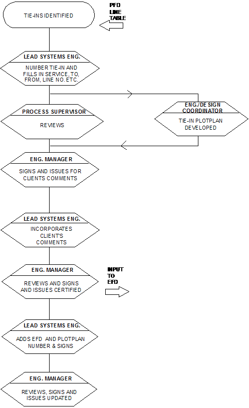
The procedure for preparation of the tie-in index is detailed below. A flowchart for tie-in index preparation is attached in 5.3. This depicts the procedure for a Company standard project.
Using data from new/existing PFD’s, new/existing line table, and/or new/existing client information, the LSE prepares the preliminary index filling in: Tie-in Number, Service, To/From, Line Number and Size, Operating and Design Pressure Temperature.
a. Index is transmitted to Process Supervisor who adds the peak and normal flow rates, and performs general review.
b. Engineering/Design Coordinator uses preliminary index information and client information to locate the layout lines entering/leaving the boundary lines.
Index is transmitted to Engineering Manager who signs it (QA) and has it issued "For Clients Comments" of "For Approval." Letter is written asking for client review and also that actual minimum and maximum pressure and temperature at battery limit, type of connection, and other client originated information to be added.
Client comments are reviewed and incorporated by the LSE. LSE signs the document (QC) and transmits it to the
Engineering Manager for issue. Engineering Manager reviews index, signs it (QA), and has it issued "Certified".
Information from the index is added to the EFD’s by the Systems Engineers. The LSE adds the EFD and plot plan drawings numbers to the index.
The LSE signs the document (QC), and transmits it to the Engineering Manager for issue. Engineering Manager reviews the index, signs it (QA), and has it issued "Updated."
4.2.6 Preparation of Miscellaneous Materials (MM) List
4.2.6.1 Introduction
The miscellaneous material list, documents materials that are not covered in other standard specifications and lists (such as the C-1 specification for piping items). The Engineering Manager has the overall responsibility for the development and maintenance of the miscellaneous materials list and for the specification. The responsibilities of the Systems Engineers and the Piping Engineer are limited to identification and technical specification of miscellaneous materials. Process Engineers assist, as required, in this task.
4.2.6.2 Procedure
Parallel with the development of the EFD’s, each Systems Engineer identifies the miscellaneous items requiring MM numbers and specification by adding the notation "MM" to the flow diagrams, and giving it a unique sequence number.
The LSE is responsible for maintaining an MM-item list, ensuring uniqueness of each number.
The Systems Engineer adds the MM item number to the EFD.
After the "For Client Comments" or "For Approval" issue of EFD’s, it may be assumed that a large percentage of MM items have been identified and numbered. The MM list is issued "Preliminary” to the Engineering Manager.
The MM list is revised by the LSE after the "Certified" issue of the EFD's to reflect revised and new or deleted items. The MM list is issued "Certified".
The MM item list is revised and reissued during detailed design as required. The LSE maintains a master MM list markup between issues.
5. Flowcharts
5.1 Flowchart for EFD Preparation
5.2 Flowchart for Line Table Preparation
5.3 Flowchart for Tie-in Index
6. References
| Document Number | Title | Level | |
|
6.1 |
BN-DG-UD01 |
Guide for Checking of Flow Diagrams and Line Designation Tables | 5 |
|
6.2 |
BN-W-UE301 |
Work Instruction for the Numbering of Project Documents | 4 |
|
6.3 |
BN-W-U012 |
Work Instruction for Document Issue Code and Change Identification | 4 |
|
6.4 |
CM-PE-504 |
Procedure for the Production of Engineering Documents | 2 |
|
6.5 |
BN-W-UD301 |
Work Instruction for Preparing Manual Technical Drawings | 4 |
|
6.6 |
- |
- | - |
|
6.7 |
BN-DG-UD008 |
Design Guide for the Preparation of Flow Diagrams | 5 |
|
6.8 |
BN-W-UE307 |
Work Instruction for Change Control of Engineering Flow Diagrams | 4 |
|
6.9 |
BN-EG-UE208 |
Engineering Guide for the Preparation of Flow Diagrams (in preparation) | 5 |
7. Attachments
- Departmental Split of Work
- EFD Technical Content for Major Issues
- Line Table Technical Content for Major Issues
1. Departmental Split of Work
| Process/Systems Engineering | Other | ||
| a. | Engineering Flow Diagram (EFD) Tasks |
|
|
| Overall responsibility (see Paragraph 3) |
X
|
||
| Layout and Format |
X
|
||
| Piping Class Selection |
X
|
Piping Engineering, Mechanical (Assist) | |
| Mechanical Details (P, vendor designed T, G & H equipment) |
X
|
Mechanical Engineering (Assist) | |
| Valve Tagging |
X
|
||
| Pickling/Chemical Cleaning Philosophy |
X
|
Mechanical Engineering and Piping Engineering (Assist) | |
| Pickling/Chemical Cleaning Details |
X
|
||
| Maintenance Requirements |
X
|
||
| Flowsheet Revisions Sheets |
X
|
||
| Startup/Test Run Requirements |
X
|
||
| Decommissioning (Pumpout) Details |
X
|
||
| Sample Points |
X
|
||
| Control Philosophy |
X
|
||
| Application of Control Philosophy |
X
|
Control Systems (shared) | |
| Process Details (minimum elevations, tracing, etc.) |
X
|
||
| Line Sizing |
X
|
||
| Safety Systems |
X
|
Control Systems (shared) | |
| Tracing Requirements for Process Reasons |
X
|
||
| Tracing Requirements for Mechanical Reasons (winterization, etc.) |
X
|
||
| Instrumentation Number and Details |
|
Control Systems | |
| b. |
Demolition Diagram Tasks |
|
|
| Overall responsibility |
X
|
||
| Identification of equipment piping and instrumentation to be demolished |
X
|
assistance from piping and control systems | |
| c. | Line Table Tasks |
|
|
| Overall responsibility |
X
|
||
| Assigning line Number, fluid from/to, material class, Testing pressure and medium, tracing type, EFD drawing number |
X
|
||
| Establishing line size, operating pressure and temperature, design pressure and temperature, maximum temperature for thermal stress, process tracing needs |
X
|
||
| Insulation requirements for mechanical reasons (personnel protection, etc.) |
X
|
assistance from insulation engineering | |
| Assigning insulation thickness and paint code |
X
|
assistance from insulation/painting/ acoustical engineering | |
| d. |
Tie-in Index Tasks Complete responsibility |
X |
|
| e. | Miscellaneous Material (MM) List Tasks |
|
|
| Overall responsibility |
X
|
project engineering | |
| Assigning MM numbers |
X
|
project engineering | |
| Preparing requests for purchase |
|
||
| Process specification requirements |
X
|
||
| Mechanical specification requirements |
X
|
project engineering assistance other disciplines as required |
2. Engineering Flow Diagram Technical Content for Major Issues
| Engineering Flow Diagram Tasks | For Int. Comments | For Client Comments/ Approval | Approved/ Certified for Design | As Designed | As Built | |
| 1. | Layout equipment; establish quantity of equipment in each diagram, relative equipment size and relative equipment elevations. Show the number and name of all equipment. Show package equipment as an enclosed box with no details. |
X
|
|
|
|
|
| 2. | Establish the layout of each diagram |
X
|
|
|
|
|
| 3. | Show valving, including location, as shown as much as possible. Location is shown in two ways: dramatically and by notes. |
X
(start) |
X (complete)
|
|
|
|
| 4. | Show line numbers. |
X
(start) |
X (complete)
|
|
|
|
| 5a. | Show line sizes, material classes, class breaks, and tracing. |
X
(start) |
X (complete)
|
|
|
|
| 5b. | Show piping valve tag numbers (if required). |
|
|
X
|
|
|
| 6. | For RE&C designed equipment, show nozzle sizes and relative locations using RE&C drawings and specifications. |
|
X
|
|
|
|
| 7. | Show startup and decommissioning details. |
|
|
|
|
|
| 8. | Show UDD tie-in diagram numbers. |
|
X
|
|
|
|
| 9. | Show instrument numbers |
|
X
|
|
|
|
| 10. | Show how ESD systems function (i.e., a written outline of causes and effects). |
|
|
X
|
|
|
| 11. | For vendor design and equipment, where complete information is available on the “certified” specification, show nozzle sizes and relative locations and other details. |
|
|
X
|
|
|
| 12. | For vendor designed package equipment show the package outline and piping, Instrument and control interfaces, including piping interface sizes. |
X
|
|
|
|
|
| 13. | For vendor designed equipment show the vendor details, including piping, valving, instruments, controls, and special details (e.g., vents, drains, leak-offs, gland condensers, governor valves, trip/throttle valves for a turbine; instruments, burner valving, and controls for heater, etc.). This detailed information typically would be show on an auxiliary engineering flow diagram or on a vendor drawn diagram. |
|
|
|
X
|
|
| 14. | Add client comments (if required) |
|
|
X
|
|
|
| 15. | Show notes for non-standard controls. Also show ESD Systems. |
|
X
|
|
|
|
| 16. | Show process vents and drains, sample connections and chemical cleaning connections. |
|
|
X
|
|
|
| 17. | Show in-line instrument sizes. |
|
|
X
|
|
|
| 18. | Show control valve manifold valve sizes and pump suction and discharge valve sizes. |
|
|
X
|
|
|
| 19. | Show pressure safety valve sizes. |
|
|
X
|
|
|
| 20. | Show revisions to the piping resulting from the detailed piping design. |
|
|
|
|
X
|
| 21. | Show revisions resulting from field changes. |
|
|
|
|
X
|
NOTE: If definitive estimate is required between the “For Client Comments” for “For Approval” issue and the “Certified” issue, then a “For Definitive Estimate” issue may be required incorporating some of the technical content not required until the “Certified” issue, i.e., valve size as in Item 16., insulation and paint requirements, etc.
3. Line Table Technical Content for Major Issues
| Line Table Issues | |||
| Preliminary Issue to UPE | For Comments | For Client Comments/ For Approval | |
| Cover Sheet |
X
|
X
|
X
|
| Line Number |
X
|
X
|
X
|
| Fluid |
X
|
X
|
X
|
| From, To Flow Diagram No. |
X
|
X
|
X
|
| Line Size |
X
|
|
|
| Operating Pressure and Temperature |
|
X
|
X
|
| Design Pressure and Temperature |
|
X
|
X
|
| Insulation Code (HC, CC, PP) |
|
X
|
X
|
| Tracing |
|
X
|
X
|
| Material Class |
|
X
|
X
|
| Maximum Temperature for Thermal Stress |
|
|
X
|
| Insulation Thickness |
|
|
X
|
| Paint Code |
|
|
X
|
| Testing Medium |
|
|
X
|
| Test Pressure |
|
|
X
|
| Service Classification |
|
|
X
|