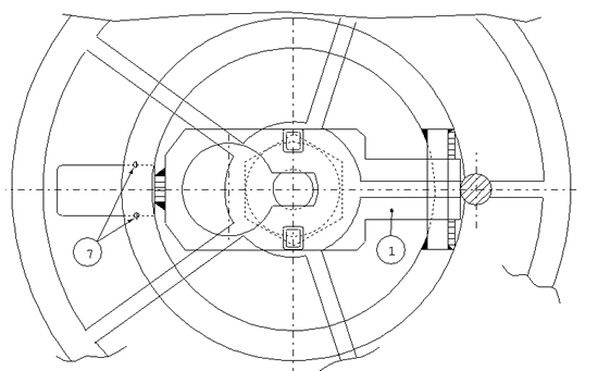
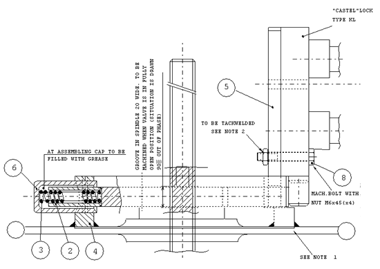
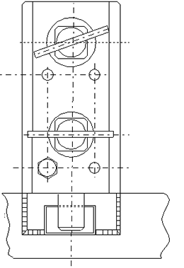
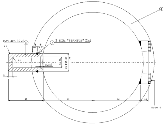
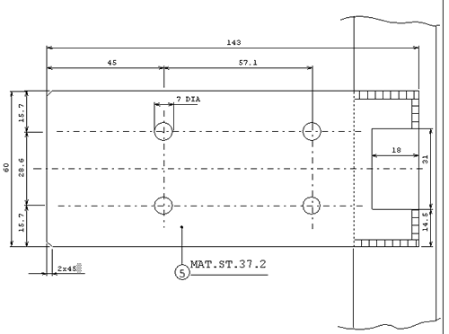
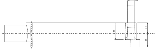
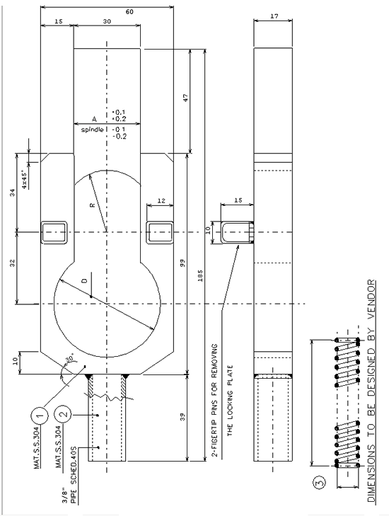
Design standard for valve locking arrangement. Detail dimensions are depending client requirements and vendor data for locking device.
General Notes:
- Bottom of 6" pipe to be machnied at location of spokes in such a way that the bootom of the locking late is flush with the top of the yoke nut and or handwheel nut. 6" pipe to be welded at all spokes.
- Mounting, bolting-up and bolt tackwelding of the castell locks shall be carried out after the connected piping system is tested just prior to commissioning.
- All parts to be free from sharp edges.
- Lock mounting plate (pos 5) to be welded to 6" pipe (pos 4) after locking plate (pos 1) is mounted.
- Pos 4 is pipe schedule 120 (168.3 x 139.7 diam.) material API-5L
- Based on "Castel" lock type KL
|
Valve
|
Spindle Diameter
|
R
|
A
|
D
|
|
|
Size
|
150#
|
300#
|
|||
| 2" | 3/4" (19) Diam. | 3/4" (19) Diam. | 12 | 13 | 24 |
| 3" | 7/8" (22.2) Diam. | 7/8" (22.2) Diam. | 13.5 | 16 | 27 |
| 4" | 1" (25.4) Diam. | 1" (25.4) Diam. | 15 | 19 | 30 |
| 6" | 1 1/8" (28.6) Diam. | - - - | 17 | 22 | 34 |
| 6" | - - - | 1 1/4" (31.7) Diam. | 18.5 | 25 | 37 |
| 8" | 1 1/4" (31.7) Diam. | - - - | 18.5 | 25 | 37 |
| 8" | - - - | 1 3/8" (34.9) Diam. | 20 | 28 | 40 |
| 10" | 1 3/8" (34.9) Diam. | - - - | 20 | 28 | 40 |
| 10" | - - - | 1 1/2" (38.1) Diam. | 21.5 | 30 | 43 |
Details of valve locking arrangement
