")
Table of Contents
1. General
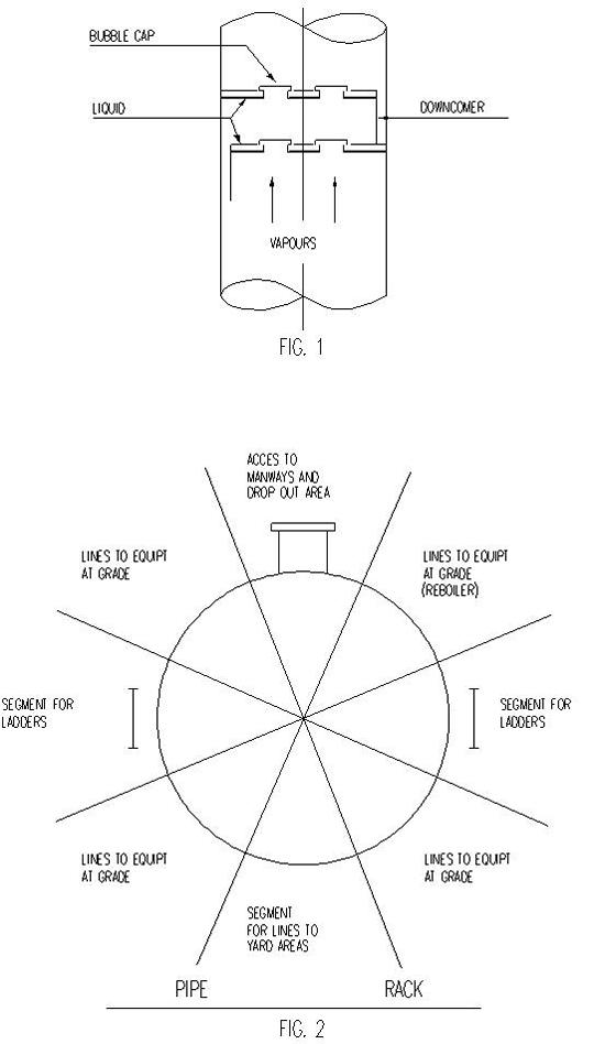
The fractionation column comprises a vertical cylinder interspaced at equal intervals with trays. Often these are in the form of simple perforated disks, but more complex arrangements occur depending upon column function. Contents are heated near the bottom producing vapours which rise up through the trays, meeting a flow of liquid passing down as a result of condensation occuring at various levels.
It is essential to ensure maximum surface contact between vapour and liquid. The lightest fractions are drawn from the highest elevations, the heaviest residue being deposited at the bottom.
2. Layout
It is necessary to establish whether column is working as a single unit or in conjunction with others similar. Dependent upon process arrangements flow may be sequential from one to the next. Thus for maximum economy order of columns must be arranged to give shortest piping runs and lowest pumping losses. Consideration should be given, where necessary, to material used, since although correct sequence may have been effected unnecessary expense may be involved with alloy lines. Such cases must be treated on their merits.
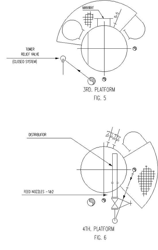
Column is interconnected with other process equipment so it must be located adjacent to pipe rack to allow piping connections to run to and from the rack in orderly fashion. Automatically this means that manways (provided for erection of trays and maintenance) should be located on the opposite side of the column away from the rack to provide suitable access for equipment required to be removed (see below figures). This is not mandatory since occasions arise when other arrangements are necessary.
3. Internals
Having located manways, orientate internal trays to ensure unimpeded access. Depending upon the type of tray used one or more downcomer partitions may be required. If these are orientated incorrectly entry will be impossible via manhole unless the column is exceptionally large. Preferably downcomers are arranged normal to manway access center line. Process connections can be located in logical sequence, starting from the top when tray orientation is established.
4. Overheads
Highest connection is the overhead vapour line which is usually connected to a condensing unit. An air fin type unit may be located on top of the pipe rack. Alternatively a shell and tube exchanger type condenser is usually located on a structure adjacent to the column (as may air fin unit).
Overhead vapour connection may project vertically from top of the column followed by a 90° bend or it may emerge from the side at 45°, using an integral projection extending up almost to the center top inside the head (see below figure 9).
The latter is more economic in piping since it eliminates use of some expensive fittings especially when large diameter overhead lines are involved. It also makes piping supporting simpler as use of a 45° elbow enables pipe to run down close to the column. Disadvantage is greater rigidity making stress analysis more difficult.
Often permitted pressure drop between outlet nozzle and exchanger is low (i.e. approximately 0.5 PSI) thus it is essential to obtain straightest and shortest run possible. If connection is from the top special arrangements must be made for supporting the line which is often large diameter.
The condenser is usually self draining. Often some of the condensed liquid is required to be pumped back into the column (reflux). Thus the condensed liquid flows by gravity to a reflux drum situated immediately below the exchanger. This drum can also be mounted in the same structure supporting the exchanger. This is important since if it were located elsewhere an additional pump would be required if the liquid had to be elevated again after flowing from the condenser.
Furthermore, since the liquid in the reflux drum has to be returned to the column by a pump it is convenient to locate this underneath the reflux drum at the base of the structure.
It follows, therefore, that the orientation of the outlet of the vapour connection will automatically fix the location of the exchanger and the reflux drum or vice-versa. The reflux pump discharges back into the tower usually at a high elevation, and since the piping should be straight and as short as possible, it will probably come up at the side as the vapour connection.
5. Reflux
Trays are numbered starting from the top. The first downcomer is therefore an odd one. Often the reflux connection is located above the top tray (see below figure 3). This means that orientation of the odd and even trays can be fixed since to utilize the tray contact surface, the reflux connection must occur on the opposite side of the downcomer.
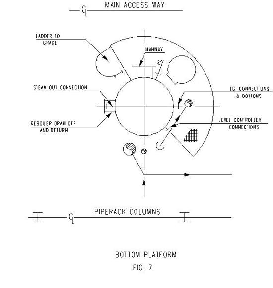
6. Feeds
The most important connections are the feeds (see figures 4 and 6). These may occur over the odd or even trays or a combination of both. Their elevational location is entirely a function of process design. Depending upon this, orientation of the nozzle will follow, but ensure that the nozzle is not located behind the downcomer from the tray above. This would result in a liquid build up in the downcomer restricting flow through the tray below and preventing correct operation.
Feed connections are usually located in the tray area between the downcomers in a manner to ensure maximum use of the tray area as possible. Often an internal feed pipe or sparger is used to facilitate this.
7. Instruments
Instr ument connections must be arranged so that pressure connections are in the vapour space and temperature connections are immersed in the liquid.
Sometimes it is better to put the temperature connections in the downcomer part of the tray since the depth of liquid will be greater and it will be easier to obtain effective coverage.
Probe length and mechanical interference may prevent this, if so locate thermowell over the tray itself. This should be done only on installations where the liquid depth on the tray is sufficient (see below figure 8).
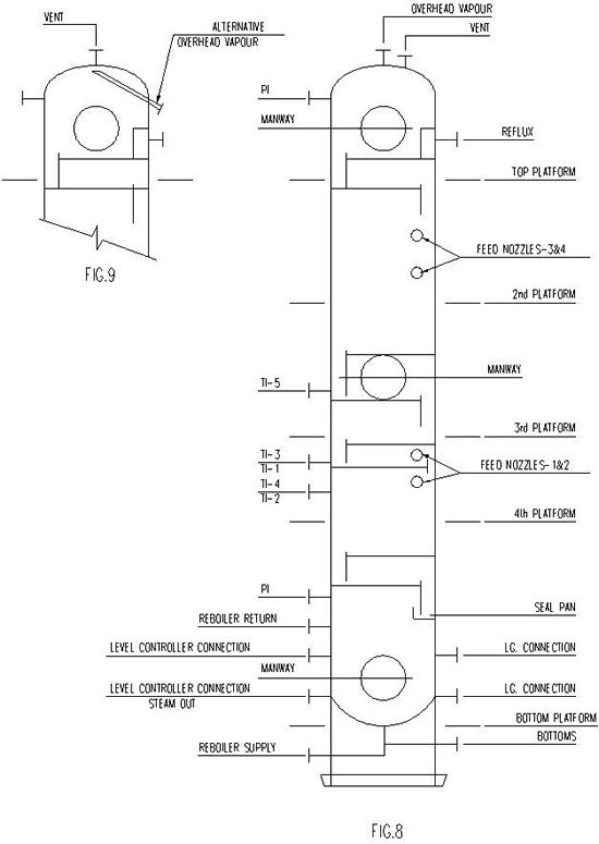
The base of the tower contains a level of liquid which is controlled by high and low level controllers, liquid level alarms and level gauges (see below figure 7). Care should be taken when orientating these instruments, that they do not obstruct access on the platform. Physical space that these instruments occupy can be excessive. Do not position immediately adjacent to ladders or manholes.
8. Reboiler Connections
Reboiler liquid and vapour connections are located either relevant to liquid head (elevation) or stress requirements, or both. Two configurations are possible :
- Vertical
- Horizontal
For horizontal reboilers, consideration must be given to shortest most direct connection route to reduce pressure drop which will probably govern design layout. In both cases there may be support problems. Usually, a vertical reboiler (thermosyphon operated) offers the easiest solution.
Flexibility is obtained on the lower connection where entry into the bottom of the tower can be varied as required and support problems are simplified.
9. Platforms
All of the above requires access of some kind. To minimise cost minimum platforming should be provided consistent with safety.
Orientation arrangements should be designed to avoid need for 360° platforms.
A platform should not extend almost entirely round the column simply to provide access to a temperature connection which could have been located on the oposite side. Where several columns may be working together, link platforms may be required to move from one to the next. In these cases strict consideration must be given to maximise economy.
Overall height is governed by a. number of trays, b. pump NPSH requirements and, c. static liquid head. This latter head necessary for thermosyphon reboiler establishes the skirt height.
10. Piping
Some circumstances require routing lines partially around the column. Should these lines cross a platform sufficient headroom clearance must be provided.
11. Top Head Relief Valves
Relief valves vary in number and size. Location can depend on whether discharge is to atmosphere or a closed system. If discharging to a closed system, locate at a convenient platform down the column above the relief header see below figure 5). If discharging to atmosphere locate on top of the column, with the open end of the discharge a minimum of 3000 mm above the top platform. For maintenance removal, valve should be located to allow top head davit to pick it up. Dependent upon size multiple relief valves may require a gantry structure on the top head.
12. Clips
Early orientation of nozzles and routing of lines allow platforms and pipe support clip locations to be passed to column vendor quickly.
It is becoming more a requirement that clips be welded on in the vessel fabrication shop particularly for alloy steels.
When locating platforms and ladders, the maximum ladder length should not exceed 9M without a rest platform.
Platforms should, where possible, be elevated 900 mm below manways.
Manways Davits or hinges should be positioned to avoid swing of cover fouling instruments or other connections.
When positioning vertical piping, to simplify supporting, attain a common back of pipe dimension from column shell of 300 mm.
Figures 1 - 8 Incl.