
")
Table of Contents
- References
- Scope
- Pressure Relief Valve Installations
- Thermal Relief Valve Installations
- Rupture Disk Installation
- Venting Atmospheric and Low Pressure Storage Tanks
1. References
The design of a relief system is governed by the following:
- API.RP520 “design and installation of pressure - relieving systems in refineries”
- British Factory Acts, in relation to steam raising plants, if applicable
- Local authorities and Clients requirements
- Good engineering practice
The design of atmospheric and low pressure venting systems are governed by the following :
- API.RP2000 “Venting atmospheric and low pressure storage tanks”
- Local authorities and Clients requirements
- Good engineering practice
2. Scope
This guide is intended to cover methods of installation for pressure relief valves and their associated pipe work and fittings.
The installation of rupture disks.
Venting storage tanks.
3. Pressure Relief Valve Installations
For general requirements of relief valves installation at vessel or pipe work, see below figures.
Relief valves should be mounted in a vertical position only.
For optimum performance relief valves must be regularly serviced and maintained. To facilitate this, relief valves should be located to enable easy access and removal. Sufficient platform space must be provided around the valve. Provision of a lifting device should be considered for large relief valves.For typical installation of relief valves and piping, see below figures.
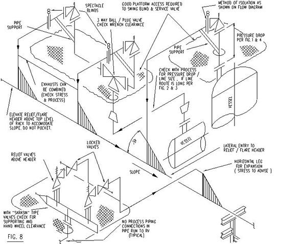
The system inlet and outlet piping shall be designed to provide for proper valve performance. To this end a complete relief system isometric showing the inlet and discharge piping of all relief valves included in the system will be produced. Below figures shows part of such a system, overall dimensions and line sizes should be included.
The system must first be approved by the Process Department for pressure drop, then by the Stress Section for stress. Should the piping be rerouted due to stress requirements Process Department must reapprove the system.
The inlet piping to a relief valve shall be designed so that the pressure drop does not exceed 3 percent of the relief valve set pressure, see below figures.
The most desirable installation is that in which the nominal size of the inlet branch piping is the same as or greater than, the nominal size of the valve inlet flange, and in which the length does not exceed the face to face dimensions of a standard tee and weld neck flange of the required pressure class. The configuration shown on the flow diagram must always be followed.
Relief valve systems designed to discharge against a constant pressure cannot tolerate a back pressure greater than 10% of the set pressure. Balanced bellows or Balanseal type relief valves which operate practically independent of the back pressure tolerate a much higher figure, but generally the higher the back pressure the lower the capacity of the relief valve. Due to this the discharge piping should be kept as direct as possible,see below figures.
The flow diagram will determine if the discharge is to atmosphere, or to a closed discharge header, see below figures for details.
It is poor practice to mount the relief valve at the end of a long, horizontal inlet pipe through which there is normally no flow
Foreign matter may accumulate or liquid may be trapped and may interfere with the operation of the valve or be the cause of more frequent valve maintenance.
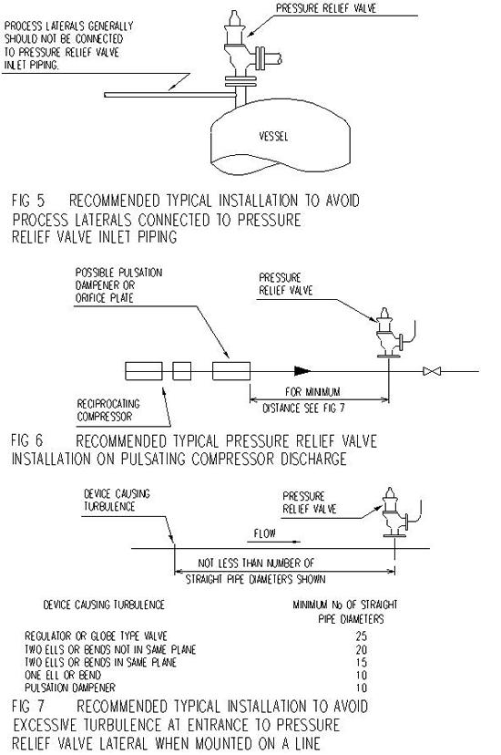
Process laterals generally should not be connected to relief valve inlet piping, see below figure 4.
Proximity of other valves and equipment, the recommendations laid down in below figures 4, 6 and 7 should be followed if possible for the minimum number of straight pipe diameters between the device causing turbulence and the relief valve. The above does not apply to relief valves fitted with stop valves, see below figures.
Relief valves discharging into a relief header must be located at an elevation above the relief header so that the discharge line is free draining. Under no circumstances may the discharge line or the relief header be pocketed.
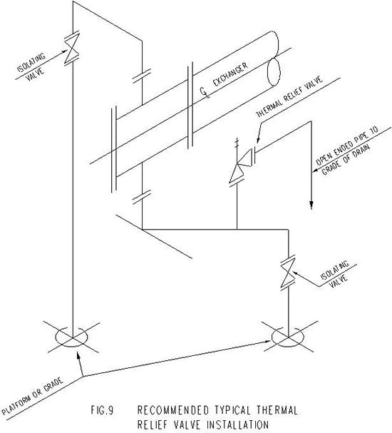
4. Thermal Relief Valve Installations
Thermal relief valves are provided on cooling services where a system can be locked in by isolating valves. The discharge from the relief valve should be piped to grade in offsite areas, to the nearest drain in process areas, follow details as shown on the flow diagram. See below figures for further details.
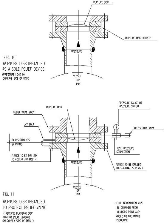
5. Rupture Disk Installation
A rupture disk device is a nonreclosing pressure relief device actuated by inlet static pressure and designed to function by the bursting of a pressure containing disk. The disk may be made of metal or carbon graphite and housed in a suitable holder.
The purpose of installing a rupture disk up stream of a relief valve is to minimise the loss by leakage through the valve of valuable, noxious or otherwise hazardous materials or to prevent corrosive gases from reaching the relief valve internals, see below figure 11. Typical bursting disk installation at a relief valve.
The installation of a rupture disk may be called for down stream of a relief valve. In this case its purpose is to prevent corrosive gases from a common discharge line reaching the relief valve internals.
Rupture disks may also be installed as a sole relief device, see below figure 10.
Rupture disks must always be installed as shown on the vendors drawing. For example of a Concave installation see figure 10 and a Convex installation see figure 11.
6. Venting Atmospheric and Low Pressure Storage Tanks
Determination of venting requirements
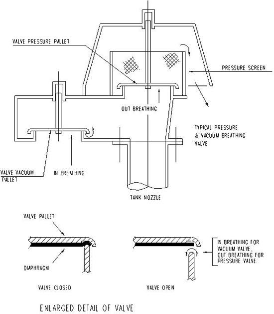
Inbreathing results from maximum outflow of oil from tank, or from contraction of vapors caused by maximum decrease in atmospheric temperature. A vacuum breaking device is fitted directly to the line or vessel to prevent its collapse when the internal pressure falls below atmospheric. If the admission of oxygen into the process is hazardous, a inert gas supply is connected to the vacuum breaker via a pressure reducing valve. Follow the system defined on the Flow Diagram.
Outbreathing results from maximum inflow of oil into tanks and maximum which result from maximum increase in atmospheric temperature (thermal breathing). One of the following devices may be specified on the flow diagram.
Relief valve may be used either discharging to atmosphere or into a closed system.
Open vent with flame arresting device. Manhole or gauge hatch that permits the cover to lift.
Pressure and vacuum breathing valves are designed to prevent evaporation from storage tanks, but to allow breathing when the pressure or vacuum exceeds that specified. For details see below figures..
Figures 1 - 8 Incl.
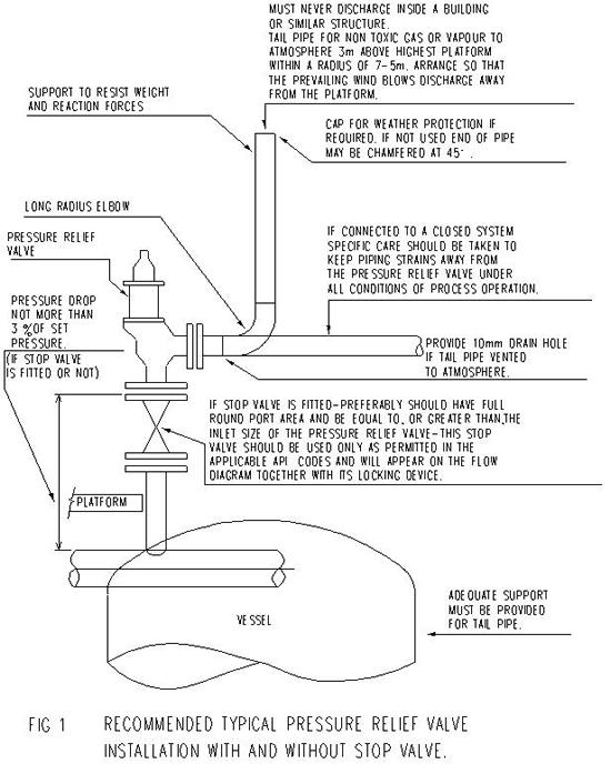
RECOMMENDED TYPICAL RELIEF VALVE INSTALLATION (BASED ON API RP 520)
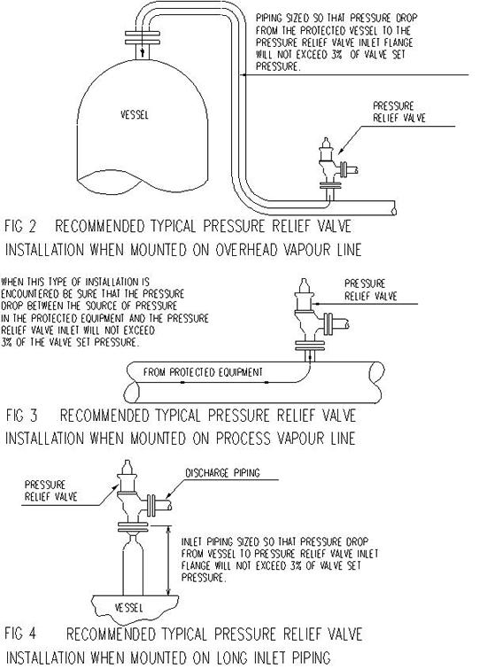
RECOMMENDED TYPICAL RELIEF VALVE INSTALLATIONS (EXTRACTED FROM API RP 520)
RECOMMENDED TYPICAL RELIEF VALVE INSTALLATIONS (EXTRACTED FROM API RP 520)
RECOMMENDED TYPICAL RELIEF VALVE INSTALLATION
RECOMMENDED TYPICAL RELIEF VALVE INSTALLATION
RECOMMENDED TYPICAL RUPTURE DISK INSTALLATION
TYPICAL PRESSURE & VACUUM BREATHING VALVE