
")
Table of Contents
1. General
2. Orifice Flanges
3. Selection of Pipe for Meterruns
4. Installation Requirements
Attachments:
Orifice Run Assemblies:
A Weldneck and Slip-on
B Holding Rings
C Pipe Taps
D Meterrun with Corner Taps (1/4” and 1/2”)
E Meterrun with Corner Taps (1” and 1 1/2”)
F Prefabricated Meterruns (2” and above)
Reference Specifications
BN-SP-K1 Engineering and Design Specification for Instrumentation
BN-SP-C1 Specification for Piping Design
BN-SP-C2 Specification for Piping Materials
BN-SP-C3 Specification for the Preparation of Ferrous Pressure Piping
1. General
1.1 The primary consideration in the design and fabrication of orifice runs is accuracy.
Orifice meter run application may be divided in two categories:
a. Standard applications
b. High accuracy for accounting and billing applications
High accuracy services will be identified separately.
1.2 Errors in orifice flow measurements of up to 10%, or larger, can be attributed to:
- Disturbances in the flow profile upstream and downstream of orifice run
- Flange misalignment
- Pipe eccentricity
- Pipe wall roughness
- Pipe out of round
- Un-bored backing ring well instructions or welding bead penetrations.
2. Orifice Flanges
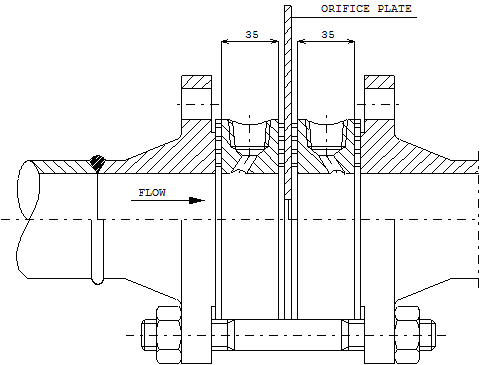
2.1 Orifice flange for run installation should be so constructed, machined and attached to the that the inner surface of the passage extends through the orifice flange so that there is no recess at the orifice plate.
The flange bore and the section of pipe shall be of the same internal diameter.
3. Selection of Pipe for Meterruns
3.1 Standard Applications
3.1.1 Meterrun pipe shall be selected from commercially available piping material as made available for the project.
3.1.2 The selection shall be based on more visual inspection on the following points:
- Pipe section is straight over the required minimum straight length. (Refer BN-SP-K1)
- The pipe bore is circular over the entire length.
- The inside surface of pipe section should be free from pitting, grooves and not be encrusted.
- Rough internal welds, longitudinal or circumferential are not allowed.
3.2 High Accuracy Applications
3.2.1 In addition to the selection requirements as applicable to meterrun piping for standard application the assembly for high accuracy applications shall comply with the following requirements of ISO recommendation R5167. The will be applicable to the meterrun assembly including orifice flanges and the attached pipe sections.
a. Inside pipe walls shall be smooth, roughness not be exceed 300 micro inches (Ra as per ISO R 468) for meterruns 2 inch and above.
Below 2 inch, meterrun roughness shall be as specified on the drawings
Pipe wall roughness to be accessed by tactile comparison against standard roughness scales.
b. The out-of-roundness tolerance over an up stream length of at least 2 diameters measured from the upstream face of the orifice plate should not exceed 0,3% from the calculated mean inside diameter.
The mean internal diameter of the down stream length, considered along a length of at least 2 diameters should not differ from the mean upstream diameter by more than ±2%. Measurements shall be taken at locations stipulated in ISO recommendation R5167.
3.2.2 Grooves, scoring pits, ridges,shoulders, distortions, etc. which affect the inside diameter more than the specified tolerance shall not be permitted. When these measurements are exceeded, the irregularities may be corrected by filling-in, grinding or filling.
3.2.3 Pipe sections may be specially selected from commercial pipe but shall comply with all the requirements as per piping specification BN-SP-C2.
Fifteen diameters of the special pipe upstream of the orifice is sufficient and standard pipe of same schedule and published inside diameter may be used for added straight length.
For smaller sizes (2,3 and 4 inches) the pipe sections shall preferably cover the entire straight length required.
Alternatively, wherever the highest accuracy is required, the upstream internal diameter of the pipe shall be bored for a distance of at least 4 diameters. Wall thickness shall not deviate more than 12,5% of the published dimensions.
3.2.4 Each section of meterrun piping shall have its average internal diameter stamped on a stainless steel nameplate welded to the flange.
3.3 Prefabricated Meterruns
Prefabricated meterruns shall follow the requirements of high accuracy.
Prefabrication may be specified to ensure a correctly dimensioned and installed orifice assembly.
For meterruns below 2 inch nominal line size individual flow laboratory calibration might be required as errors caused by the roughness of pipe wall become more pronounced.
4. Installation Requirements
4.1 Welding Procedures
4.1.1 Welding procedures and heat treatment shall comply with BN-SP-C3 specification for prefabrication of ferrous pressure piping.
4.1.2 Reduction of the diameter of the pipe or distortion caused by welding should be eliminated.
4.1.3 If there is any internal roughness at welds of the assembled meterrun, it should be ground smooth and flush with wall of pipe.
4.1.4 Flanges must be welded to pipe concentrically with flange faces exactly at 90º to center line of pipe although a tolerance of 3,5 mm per meter is permitted.
4.2 Orientation
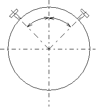
4.2.1 Pressure taps should be orientated as shown on the following table unless specified otherwise on the piping isometric.
|
|
|
Line |
Flange Class | ||
|
Size |
150# |
300# |
600-900# |
|
2” |
45 º |
45 º |
45 º |
|
3” |
45 º |
45 º |
45 º |
|
4” |
45 º |
45 º |
45 º |
|
6” |
45 º |
30 º |
30 º |
|
8” |
45 º |
30 º |
30 º |
|
10” |
30 º |
45 º |
45 º |
|
12” |
30 º |
45 º |
36 º |
|
14” |
30 º |
36 º |
36 º |
|
16” |
45 º |
36 º |
36 º |
4.2.2 Flanges should be so oriented that the jack-bolts are diametrically opposite.
4.2.3 Bolt holes of all flanges shall straddle the vertical centerline of the assembled installed meterrun.
4.3 Mounting
4.3.1 The inside diameter of the gasket must not be smaller than the inside diameter of the pipe, and the gasket must be positioned concentrically.
4.3.2 A pair of break-out flange may be installed, without affecting accuracy, at a minimum of 5 diameters downstream from the orifice to allow inspection of the orifice run.
4.4 Storage
4.4.1 Internal surfaces of the pipe sections shall be preserved to prevent corrosion during storage and installation.
4.4.2 For protection during shipment and outdoor storage flange faces and butt well ends shall be protected/enclosed by steel plates and/or plastic caps.
Attachment “ A”
Weldneck and Slip-On Orifice Runs
Weld Neck Orifice Run
Slip-on Orifice Run
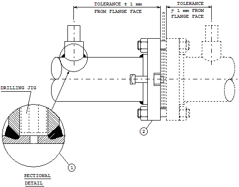
1. End of pipe should be reamed after cutting to ensure a perfectly smooth bore and should enter the flange as shown, for raised face flanges. For ring type joints the ends of the pipe should be a maximum of 3 mm from flange face.
2. The pipe should be drilled through each flange pressure tapping using a 12 mm drill for 4” bore pipe and over, a 10 mm drill for 3” bore pipe and a 6 mm drill for 2½” bore pipe and smaller.
After drilling, remove all burrs from inside of pipe and slightly round the edges of the holes with a fine emery cloth.
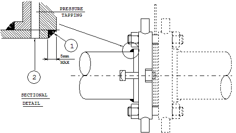
Attachment “ B”
Standard Pipe Flanges with Holding Rings
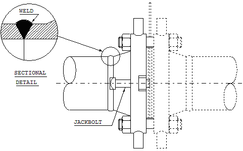
Attachment “ C “
Pipe Taps
1. The pipe tap connections should be welded to the exact locations shown on the piping isometric. The pipe should then be drilled through the connection, using a drilling jig, with a 12 mm drill for 4” bore pipe and over, 10 mm drill for 3” bore pipe and a 6 mm drill for2½” bore pipe or under. After drilling, remove all burrs from inside of pipe and slightly round the edges of the holes with a hook scraper.
2. Slip-on flanges as per pipe class with jack bolt.
Attachment “ D “
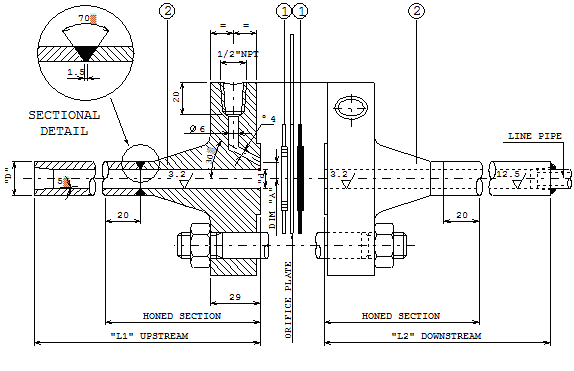
Orifice Meterrun with Corner Taps for 1/4“ and 1/2“ Pipe 600 Lb Ans
|
Line |
Flange |
d |
D |
L1 |
L2 |
“A” |
Item List |
||
|
Size |
Size |
mm |
mm |
mm |
mm |
mm |
1. |
AISI-316 spiral wound gasket with asbestos filler and |
|
|
1/4” |
2” |
7 |
21 |
350 |
125 |
7.5 |
guide ring as per API-601, 600lb ANS |
||
|
1/2” |
3/4” |
12 |
21 |
350 |
125 |
10 |
2. |
Special weldneck flange further dimensions as per |
|
|
ANSI 600 lb (with jack bolts). |
|||||||||
|
Flange facing “smooth finish 125 AARM be suit ID of spiral wound gasket. |
|||||||||
General Remarks
1. Upstream end downstream parts to be carefully drilled cylindrical and machined to the required surface roughness as indicated above in micro inches.
2. The fabrication of meterruns shall include the supply of all necessary gaskets,bolts,nuts, etc.
3. End connections to suit line pipe (see requisition).
Attachment “E “
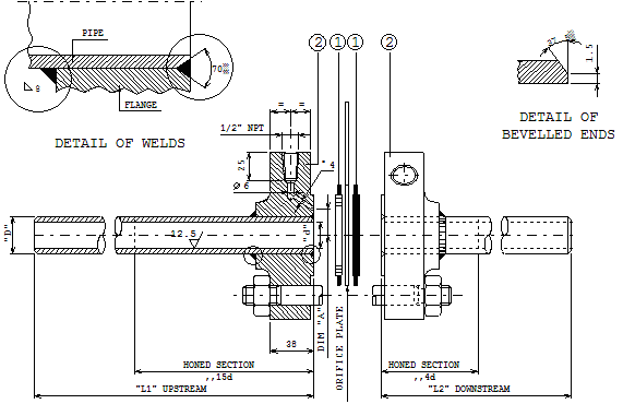
Orifice Meterrun with Corner Taps for 1” and 1 1/2“ Pipe 600 Lb Ans
|
Line |
Flange |
d |
D |
L1 |
L2 |
“A” |
Item List |
||
|
Size |
Size |
mm |
mm |
mm |
mm |
mm |
1. |
AISI-316 spiral wound gasket with asbestos filler and |
|
|
1” |
1 1/2” |
25 |
33.4 |
720 |
200 |
22 |
guide ring as per API-601, 600lb ANS |
||
|
1 1/2” |
2” |
39 |
48.2 |
1100 |
300 |
29 |
2. |
Special slip-on flange further dimensions as per |
|
|
ANS 600 lb (with jack bolts). |
|||||||||
|
Flange facing “smooth finish 125 AARM be suit ID of spiral wound gasket. |
|||||||||
General Remarks
1. Upstream end downstream parts to be carefully drilled cylindrical and machined to the required surface roughness ( micro inches ).
2. The fabrication of meterruns shall include the supply of all necessary gaskets,bolts,nuts, etc.
3. Where specified in the requisition, weldneck orifice flanges shall be used.
4. Do not use slip-on flanges for hydrogen service.
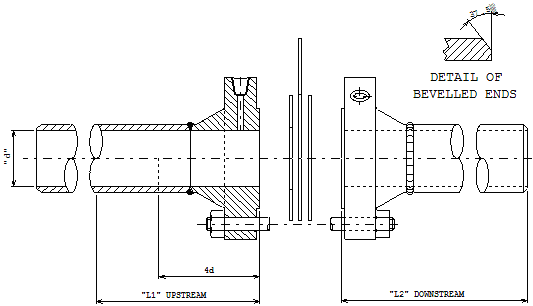
Attachment “F “
Details for Orifice Run Assembly
|
Nominal |
SPECIAL SELECTED PIPE |
|
|
Line |
||
|
Size |
L1 |
L2 |
|
Inch (D) |
mm |
mm |
|
2 |
1450 |
410 |
|
3 |
2150 |
610 |
|
4 |
2900 |
850 |
|
6 |
4300 |
1250 |
|
8 |
5700 |
1650 |
|
10 |
7150 |
2050 |
|
12 |
9000 |
2450 |
Prefabricated Meterruns for High Accuracy Applications
General Remarks
1. Machining of upstream section over a length of 4d may be necessary to meet surface roughness requirements.
2. For requirements on the orifice flanges refer to the requisition
3. Prefabrication shall include the supply of all necessary gaskets, bolts, nuts, etc.
4. Straight length requirements, as indicated on piping drawings, are to be completed with standard pipe class materials of same published internal diameter.
5. For required internal diameter, pipe schedule and rating refer requisition.