Table of Contents
1. General
1.1 Description
This specification covers the minimum technical requirements for remote control units and safety switches for local control of electrical motors. Additional information will be given in the requisition.
1.2 Standard
The remote control units and safety switches shall meet the requirements of all standards stated in the requisition.
All switches shall be of a construction suitable for application in areas with explosion danger as stated in the requisition.
Materials complying with the relevant standards of the country of origin can also be acceptable provided purchaser has approved them.
1.3 Site Conditions
Remote control units and safety switches shall suit the site conditions mentioned in the requisition and shall withstand a corrosive chemical and refinery atmosphere, with a maximum ambient temperature of 40°C and a relative humidity of 90%.
1.4 Conflicting Requirements
In case of conflicts between the conditions and documents mentioned above or between these and the specification in hand the severest requirements will govern.
Purchaser will not be obliged to check vendor’s documents such as quotations, order confirmations, drawings, etc.
Purchaser will approve them in principle only. It will be vendor’s responsibility to produce the safety switches and rotary switches in accordance with this specification in a completely functional and workmanlike manner.
A deviation from this specification will only acceptable in case vendor has specified in his quotation under the heading “deviations from specification” the requirements he cannot meet and Company has accepted this deviation in writing before order award or in the order.
Failure to do so will be interpreted by Purchaser as confirmation that Manufacturer complies fully with this specification.
2. Drawings and Data
Drawings and other technical data shall be furnished in the quantities specified in the requisition.
2.1 Information on Drawings and Data
2.1.1 Complete technical description.
2.1.2 Make and type of switch.
2.1.3 AC and DC rating of the switch with regard to inrush and breaking current.
2.1.4 Dimensional drawings, showing all dimensions necessary to design the stanchions.
2.1.5 Standards with which this material complies such as the gas group classification and temperature class.
2.1.6 Location and size of cable glands.
2.1.7 Explosion protected materials will only be acceptable if they are provided with a test certificate issued by a recognized testing authority.
3. Construction
Type-A Construction of normal switches in pressure-proof housings.
These housings shall be provided with explosion-proof gland(s) and terminal compartments as required by above mentioned standards.
Type-B Construction of switches with pressure-proof switch bodies.
In this case the enclosures do not need to be pressure-proof, and gland(s) can be of the normal type. Terminals, however, shall be of the increased safety design.
3.1 All material shall be tested, and provided with the required identification stamps for gas grouping and temperature class.
3.2 Enclosures shall be suitable for outdoor use in a heavy chemical atmosphere and coastal weather conditions without any additional protection.
Covers of the pressure-proof housings will be provided with a gasket to prevent ingress of water.
Connection bolts of the cover shall be located outside the gasket to prevent any entrance of water into the housing.
3.3 All items shall be provided with earthing screws, cable glands, plugs, terminals, etc. All spare threaded inlets shall be provided with stopping plugs. All cable entries shall be directed downwards.
3.4 Contact-rating shall be as specified in the requisition.
3.5 Metal housings shall be earthed by an earthing conductor in the cable, and by an external earthing wire.
For this reason metal housings shall be provided with 2 internal and 1 external earthing screw.
3.6 Switches shall be provided with padlocking facilities in the “off” or “stop” position, as specified in the requisition. These padlocking facilities shall be of stainless steel.
Enclosures shall be provided with an external mechanical stop in the start and stop position to prevent damage of the switch axle.
3.7 Space within enclosure shall be sufficient to allow the entry of 1 or 2 cables from below and to make the connections by means of normal screw on wire connectors or terminals.
3.8 For Type 1 a combined switch and terminal box as well as separated switch and terminal boxes will be acceptable, unless otherwise specified in the requisition.
3.9 Terminal blocks shall be made of reinforced bakelite (or equal material).
3.10 The maximum number of through connections between switch compartment and terminal compartment will be 6.
3.11 If specified in the requisition, units shall be supplied complete with moving-iron ammeter with overload scale.
3.12 All switches shall be marked as indicated in the requisition.
4. Arrangements
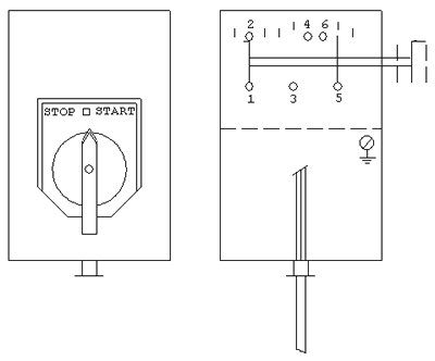
4.1 Type 1
Combined power and control cable.
Handle can turn 45° to the right as well as to the left.
Spring return from “start” to “0” position.
When standing in the “stop” position, the handle is engaged.
Padlocking in the “stop” position.
Contact 1-2 is a sliding contact which remains closed in the “0” and in the “start” position and which will be opened in the “stop” position.

4.2 Type 2
Separate control cable.
Handle can turn 45° to the right as well as all to the left.
Spring return from “start” to “0” position.
When standing in the “stop” position, the handle is engaged.
Padlocking in the “stop” position.
Contact 1-2 is a sliding contact which remains closed in the “0” and in the “start” position and which will be opened in the “stop” position.

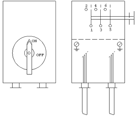
4.3 Type 3
The positions (“on” and “off”) both with engagement.
Padlocking facilities in the “off” position.


