
")
- Piping General Arrangement Drawings (Piping G.A.’s)
- Piping Isometrics 3. Piping Material List
- Piping ISO-System Drawings
- Rules for Executing Piping Design Work for Revamp Projects
- Instructions for Checking Piping Documents
Attachments
- Production Flowchart of Pipng Documents
- Drawing Symbols
- Nozzle Data
- Line Attachments
- General Abreviations
- Piping G.A. Revision List
- Free Handsketch for APD-ISO
- System Drawings Example
- Piping Material List
NOTE:
This guide lays down the standard requirements of Red-Bag.
Client’s requirements shall take priority over Red-Bag's
standard methods, when specifically directed.
1. Piping General Arrangement Drawings (Piping G.A.’s)
Preparatory Work to Produce PIPING G.A.’s
Prior to being able to produce any adequate PIPING G.A. in an efficient manner, it is essential that sufficient piping studies are prepared with the aid of agreed/approved plotplans, PEF’S, PEUF’S and Piping Data Sheets (line designation tables).
These piping studies shall then be used as “coordination studies” to inform/collect comments from other disciplines such as process engineering department, projectengineering department and all relevant design engineering departments.
If on a project a detail design model is provided, these coordination studies shall also beused to execute further design work on the model.
The interrelation of PIPING G.A. preparation with the plotplan, the piping studies, the model(if any) and the piping handsketches is shown on the production flowchart for piping designdocuments. See Attachment A.
Drawing symbols shall be in accordance with Attachment B.
Nozzle data shall be in accordance with Attachment C.
Line attachments shall be in accordance with Attachment D.
General abbreviations shall be in accordance with Attachment E.
Revisions to piping g.a.’s shall be indicated on piping g.a. revision lists per drawing issue.See Attachment F. Revisions to PIPING G.A.’S shall at all times refer to line numbers.PIPING G.A.’S shall under no circumstances be re-issued for any change which is notrelated to piping. Such a change in itself may be a necessity. It is not a reason for re-issueof the drawing unless/until it affects the piping layout.
Note: the use of clouds on PIPING G.A.’S to indicate revisions is prohibited.
Procedure for Presentation and Numbering of Documents andDrawings.
Drawing instructions
Size of sheet
A. A1 format (594 x 841) sheets shall be used.
B. The use of other than A1 format shall be discussed with the squad leader.
Scale
A. 1 : 33 1/3 shall normally be used for piping within an area, also for unit pipe racks.
B. 1 : 75 shall be used for yard rack piping plan views.
1 : 33 1/3 scale may be used for sections through rack.
C. Where there seems to be a reason for any other scale, the matter should be
discussed with the piping squad leader.
D. Dimensions shall be given in mm. No dimension less that 1 mm shall be used.Printing of notes etc. Shall not be less than 3,5 mm high. To obtain a readablelettering for microfilming.
E. A figured scale stick of 100 mm long shall be preprinted on the vellum in the marginof the drawing to indicate original scale.
Workspace
A plan shall be placed on the drawing sheet the same way it appears on the plotplan (i.e.same north arrow as plotplan). The north arrow shall be placed on all plans in the upperright hand corner of the sheet, using the standard north arrow sticker. See attachment b,sheet 1.
Fixed Items
Fixed items such as match lines, steelwork, platforms, cable trays, equipment outlines shallbe drawn on the reverse side of the vellum (equipment nozzles shall be considered as partof piping). The squad leader or his designate shall check completeness and accuracy ofscale of all basic piping g.a.’s prior to designers/draftpersons drafting the piping on the frontside of the vellum.
The scope of the drawing is determined from the “key-plan” of piping drawings. Confirm the cut off elevation and drawing title from the drawing index, prepared by the squad leader.
General Notes
General notes, reference drawings and tables shall be included in the area above the title and the issue block.
The following notes will appear on the “a” or grade drawing for each piping area.
A. Company high point of grade elevation = 100.000 mm is equal to (Client’s Name)
elevation _ _ _ _ _ _ _ _ _ _ mm.
B. For general notes and reference drawings see area identification plan BN- .... -00102.
The Nozzle Table
The nozzle table is placed at the top right hand corner of the drawing sheet. A completed example is to be found in Attachment C. Maximum use must be made of abbreviations,reference Attachment E.
Plan Views
Dimension lines defining the location of columns, steelwork and equipment shall be placed, if possible, outside the match lines. Dimension lines for piping can be placed, if more convenient or clear, inside the match lines.“Closing” dimensions will be given, the rule is “do not over dimension”. If part of a layout can be clearly shown with two dimensions, do not give four. However, to suit apd requirements,“string” dimensions for piping is mandatory. All elevations of pipe will be center line of pipe.
All dimensions and notes on a drawing shall be read from the bottom or right hand side ofthe vellum.
Design Information
Designers, draft persons, and checkers shall incorporate the latest information on a drawing by constantly checking the following document masters:
Flow Diagrams and Line Tables (Data Sheet Piping)
Plotplans and Key-Plans
Coordination Studies (Initial Plot Studies)
Stress Comments and Sketches
Equipment Drawings
Structure and Platform Drawings
Foundation and Underground Drawings
Piping Specifications
Engineering Design Guides (e.g. C1 - Issued for Job)
Job and General Standards
Pipe Sketches for Calculations by Process Department.
Should it be necessary to depart from the arrangement shown on the flow diagram orcoordination studies, the
squad leader shall be informed. If the change is agreed proceedas follows:
Flow Diagrams
The change shall be agreed with the Project Engineer, and be recorded on the master flowdiagram.
Coordination Studies
The piping squad leader shall agree to the change, and inform other sections.
Design Features
Outline all structural framing including platforms, etc. Also locate and identify structuralcolumn lines in accordance with the plot plan. Show the elevations of all platforms. Drawunderground drain tundishes, electrical- and instruments cable trays and trenches. Indicateall local electrical- and instrument cabinets and junction boxes.
For method of identifying structural columns, see Attachment B, sheet 1.
<Part removed from the public section of the website>
Methods of Presentation
To distinguish between material needed for the actual pipe fabrication in the pipe shop and erection of field material, the shop fabrication items are represented by a full (not heavy) line ______________ , and erection components like valves, blind flanges etc. are drawn dotted --------------.
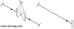
Continuation runs on terminal points or branches should only be extended to a minimum and are shown by a full thin line. Descriptions and identifications of these points are given on page 10.
Continuation runs of field fabricated pipe will be shown dotted if to be included on the isometric.

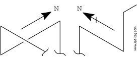
Pipe details shall have the same north orientation to the furthest possible extent.

Branch Connections
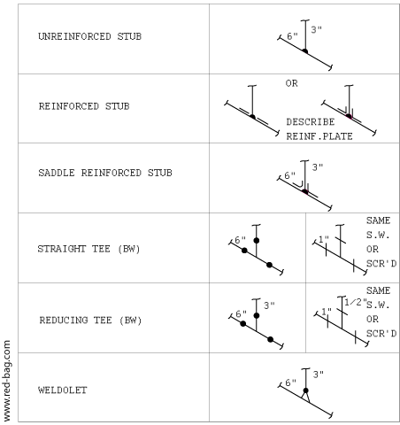
<For full version, purchase access to the registered section of the library>