Table of Contents
1 General
2 Installation at Site
3 Drawings and Data
4 Construction
This specification covers the minimum technical requirements for a static uninterruptible power supply system UPS. Additional information for each individual case shall be given in the requisition
1.2 Applicable Conditions and Requisitions
1.2.1 All latest issue of the applicable standard of the country as stated in the requisition.
1.2.2 All other (inter)national and / or local regulations applicable for this type of work, in particular IEC 146-4 and VDE 0510, part 2.
1.2.3 Purchaser’s “conditions for construction services”, no. SC 00 SEC, (if erection is part of vendor’s supply).
1.3 Site Conditions
Equipment shall suit the site conditions mentioned in the requisition, and shall withstand a corrosive chemical and refinery atmosphere.
The equipment will be located indoors at an ambient temperature between -10°C to +40°C unless otherwise specified in the requisition.
1.4 Responsibility
The vendor shall be responsible for design, fabrication, inspection, testing, transportation and starting up of the UPS unless otherwise specified.
1.5 Vendor shall supply a fully functional UPS unit, complete with all accessories.
Purchaser shall make only external cable connections for power supply to (AC and DC connection from battery) the UPS and the outgoing supplies to the consumers as well as the connection for the combined alarm cable.
1.6 Conflicting Requirements
In case of conflict between the conditions and documents mentioned above or between these and this specification, the severest requirement will govern. In case of conflict between this specification and the requisition, the requirements in the requisition will govern. Purchaser is not committed to check vendor’s documents like quotation, order confirmations, drawings, etc. Purchaser will review these in principle only. It will remain the responsibility of the vendor to make the UPS in accordance with this specification in a fully functional and workmanlike manner.
A deviation from the requisition (of which this specification forms part) is only acceptable in case vendor has specified in his quotation under heading “deviations from specification” the requirements he cannot meet and Badger has accepted these deviations in writing before ordering or in the order.
Failure to do so will be interpreted by purchaser as confirmation that manufacturer complies fully with this specification and any subsequent extra costs that may arise as a result shall be borne by the manufacturer.
1.7 The entire system shall give the maximum of safety to operating and service personnel. Even in case this requires more provisions than prescriptions by law, it shall be vendor’s responsibility to include these provisions.
2 Installation at Site
2.1 Where site erection is part of vendor’s supply the following shall be supplied by others.
2.1.1 All outgoing power cables and connections of these cables to vendor’s equipment.
2.1.2 Civil provisions outside vendor’s equipment, however, this applies only in case the necessary information has been transmitted by vendor to Badger within 4 weeks after placing of the order (see item 3.3).
Provisions announced at a later date shall be for vendor’s account.
2.2 Transport and Off-Loading Facilities on Site
2.2.1 In general, cranes which are available on site may be used by vendor for his own account and under his own responsibility. Availability of cranes and/or other necessary equipment shall be verified with the construction superintendent or his representative on site at least 1 week before arrival of the equipment.
2.2.2Transport to the relevant station shall be carried out:-
By vendor or by subcontractor of vendor with or without vendor’s supervision
- By others if specified in the requisition.
In all cases, transport, temporary protection of equipment (in case unloading on the same day is impossible or because of the weather conditions) and/or other handling procedures shall be carried under vendor’s full responsibility and for vendor’s account. Parts of equipment damaged during loading, unloading and transport shall be replaced immediately free of charge and without any time delay to the final delivery time stated in the order.
In no way it shall be possible for vendor to withdraw his responsibility for transport and/or storage of his equipment till final written take over by the field representative.
3.1 Quantities of Drawings
Drawings and other technical data shall be furnished in quantities as specified in the order. Language on the drawings shall be stated in the requisition.
3.2 Drawings and Information to Be Furnished with the Quotation
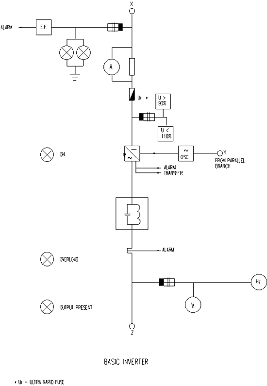
3.2.1 One line diagram showing all meters, transformers, control devices, batteries etc.
3.2.2 Control diagrams e.g. oscillator unit, voltage regulating equipment.
3.2.3 Data indicating the short circuit capacity of the inverter (maximum fuse size) and components.
3.2.4 A list of subvendors for all major equipment and components bought from others.
3.2.5 Manufacturer’s leaflet giving a complete description of the unit.
3.2.6 Completed requisition.
3.2.7 Outline drawing(s) showing overall dimensions, required clearances and set-up of arrangement.
3.2.8 Quantity of heat generated at no-and full load.
3.2.9 Front view drawing showing main equipment, metering, position of alarms and the switches.
3.2.10 Approximate weight of the unit and the battery including storage rack.
3.2.11 Capacity of battery in relation to the temperature.
3.2.12 The continuous and the momentary rating, (momentary rating in seconds) of the inverter.
3.2.13 Noise Spectrum Octave band, maximum sound pressure level in dB (RE 10-12 W).
3.3 Drawings and Data to Be Submitted for Approval after Ordering
3.3.1 Within 4 weeks after receiving the order vendor shall submit following drawings:
All drawings as per item 3.2, however, brought in line with Company’s certified requisition and comments received during the bidding stage.
3.3.2 Within 2 weeks after placing the order vendor shall submit following drawings:
Drawings showing all civil provisions to be made by others including cable holes etc. Drawings shall show the weight of equipment.
3.3.3 Schematic control diagrams but now complete with terminal and wire numbers.
3.3.4 All documents shall be marked with purchaser’s order number.
3.4 Drawings and Data to Be Sent in for Construction
Within 2 weeks after the drawings and data as per item 3.3 have been returned to vendor, vendor shall re-submit same drawings but now corrected.
3.5 Instructions, Service Manuals
8 weeks before the delivery date indicated in the order, vendor shall supply installation instructions. Immediately after testing in the factory vendor shall supply service manuals in the quantity as given in the requisition. All documents shall be in the language as stated in the requisition.
4.1 Cabinets
4.1.1 Panels shall be of the freestanding sheet steel type, without back access. Doors shall be provided with a lockable latch and shall be of a rigid construction.
4.1.2 All cables shall enter the panel through the bottom, unless otherwise specified in the requisition. Vendor shall provide suitable cable clamping facilities, undrilled glandplate(s), etc.
4.1.3 Panel(s) will be provided with adequate natural ventilation facilities. Degree of protection according IEC Publication 144 shall be IP54 and IP20 when the cabinet door is open. Ventilation openings shall be provided with a very small gauge meshwire to prevent entrance of insects. Panels shall be vermin proof.
4.1.4 Panels shall be constructed such that trouble shooting and replacement of components is possible from the front, thereby avoiding dismantling of heavy components as much as possible.
4.1.5 Panels shall be provided with a copper groundbus mounted direct to the structure of the unit with two external connection points (M 8). Vendor shall provide grounding facilities for all external cabling on the groundbus. (No threading in the groundbus).
4.1.6 The minimum size of the indicators in the front of the panel shall be 96 x96 mm. Indicators shall be flush mounted.
4.1.7 All doors on which switches, metering equipment signal lamps etc. are mounted, shall be provided with an insulating cover behind the equipment. The same doors shall be provided with a flexible ground wire to the panel structure.
4.1.8 The panel shall be provided with a mimic diagram showing the possibilities of supply to the consumers.
4.1.9 All switches shall be made of thermosetting material.
4.1.10 The external and internal parts of enclosures shall be painted according to the supplier’s standard paint procedure. The paint system shall be suitable for the site conditions mentioned. All painting damaged during loading, transport, erection, testing etc. shall be repaired with the same type of paint applied in the factory. Color of the panel(s) shall be supplier’s standard finish.
4.1.11 Nameplates shall be provided for alarms and other metering equipment. Markers shall be applied on components. All nameplates shall be white with black engraving. Nameplates shall not be glued but fixed with small bolts/nuts.
4.1.12 All wiring shall be identified by ferrules at each end of the conductor. Two wires on the same terminal are not permitted.
4.2 Rectifier
4.2.1 The rectifier shall be connected to a three phase system, unless otherwise specified in the requisition and shall be natural aircooled.
4.2.2 The rectifier shall be automatically switched to boost charging or trickle charging as required by discharge conditions of the battery without disturbing the static inverter.
Boost charging shall be adjusted such that if the battery has been completely discharged, and inverter is fully loaded, once the battery is being fully loaded, the rectifier shall supply in addition to the inverter load the float charge current of the battery.
Manual inititiating of boost charging shall be controlled automatically such that boost charging will end if battery condition requires so.
4.2.3 A solid state rectifier shall be used.
4.2.4 The rectifier shall have sufficient overload capacity to permit the UPS to ride though a fault on the output bus of inverter.
4.2.5 Semi-conductors of the rectifier and the inverter shall be protected against failures by fast acting, current limiting fuses, such that a fault shall not cause any damage to the healthy semi-conductors.
4.2.6 If semi-conductors are installed in parallel, balancing reactors shall be provided.
4.2.7 The UPS shall remain fully functional within the limits as given in the requisition when the battery is disconnected.
4.2.8 The AC input shall be protected against network disturbances (spikes from static discharges etc.) such that influence of the disturbances will not cause damage to any part of the equipment. Vendor shall prepare a test of the surge arrestor at the factory, or produce a test report from manufacturer.
4.3 Battery
4.3.1 The battery shall be of the sealed, maintenance free, lead-acid type, unless otherwise specified in the requisition.
4.3.2 The battery shall be able to give full power during the specified time under the lowest specified ambient temperature.
4.3.3 The battery shall be able to takeover the full load from the network without voltage drop of the static inverter or interruption of the power supply to the consumers.
Also a momentary interruption or voltage drop shall not be acceptable.
4.3.4 Life time of battery shall be 10 years minimum.
4.3.5 The battery shall be located in racks within the UPS cabinet or in a similar matching cabinet located next to the UPS cabinet.
4.3.6 The rms value of the AC current ripple in the battery circuit (i.e. the ripple caused by the rectifier combined with the distorsion generated by the inverter load) shall be limited to 5A per 100Ah battery capacity. (Ref VDE 0510, part 2, paragraph 6.5).
4.3.7 The battery shall be protected with a suitably rated circuit breaker with position indication alarm contact.
4.4 Inverter
4.4.1 In normal operation the frequency control of the static inverter will come from the network, controlling a stabilized free running oscillator. The inverter adapts itself to mains frequency variations. After a failure of the network or when a great frequency difference occurs (1%) the oscillator of the static inverter shall take over the frequency control, unless otherwise specified in the requisition.
4.4.2 The frequency and phase of the output of the static inverter shall run synchronized with the network, but shall not be normally connected in parallel with the network.
4.4.3 The output voltage shall be sinusoidal and galvanically separated from the network voltage.
4.4.4 The power factor of the connected load will be between 0,70 lagging and unity unless otherwise specified in the requisition.
4.4.5 The voltage and frequency tolerances of the secondary side of the static inverter shall be:
-
Steady state voltage regulation plus and minus 2% over the combination of load variations from 0-100% of the rated load with rated load power factor and minimum to maximum battery voltage.
-
Frequency regulation of the inverter between plus and minus 0.5%, the oscillator frequency shall be independant of the connected load of the UPS unless otherwise stated in the requisition.
- Transient voltage regulation plus and minus 10% for 100% load switching or transfer, recovery to 100% of steady state voltage shall be within 50 ms.
4.4.6 The inverter shall be protected against overload and short circuits by means of suitable current limitation and fast acting fuses (see paragraph 4.2.5.). The inverter shall provide at least 200% of the rated current during above conditions.
4.4.7 The inverter shall be capable of supplying a non linear (e.g. switched mode power supply) load of up to 60% of rated UPS output capacity with less than 5% total harmonic distortion (i.e. 5% total distortion between that generated by the load combined with that developed in the UPS).
4.4.8 The voltage and frequency setting shall be adjustable within their ranges by means of a simple potentiometer with a lockable control setting.
4.5 Changeover System
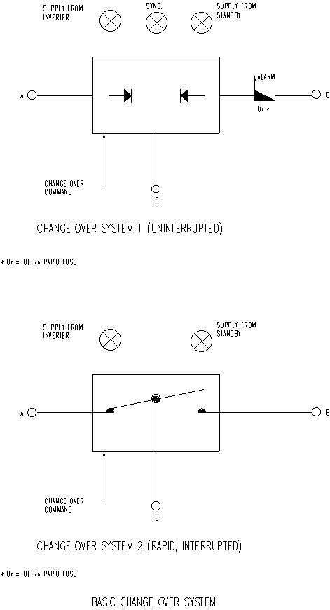
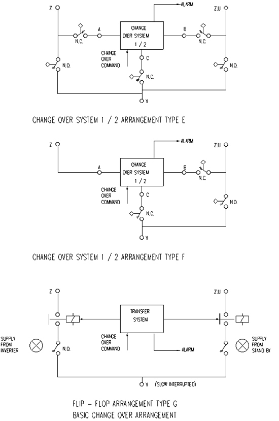
4.5.1 The changeover system may consist of:
- A static changeover switch
- A mechanical changeover being:
- A changeover consisting of a transfer switch (quick type)
- A changeover built up from two separate switching elements (slow type)
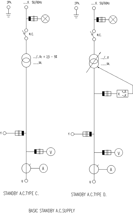
4.5.2 The static changeover switch shall be equipped with a fast acting fuse in the standby supply line (provided standby supply is of the transformer type).
4.5.3 The static changeover switch shall be a complete self supporting unit, e.g. firing pulses, etc. shall be taken from the sources supplied to it.
4.5.4 Vendor shall provide facilities such, that a bypass can be made without interruption with a manual operated switch.
If the inverter is supplying the load, engaging of the manual switch shall cause a load transfer to the static supply, before the manual switch is closed.
When the load shall be supplied again by the inverter, first the static standby switch shall be fired, the bypass switch shall be opened, immediately thereafter the inverter shall be started manually, followed by an automatic changeover to the inverter.
4.6 Transformers, Reactors, Chokes
Power transformers shall be of the separate winding type. Construction of the above items shall be specially designed to restrict noise an absolute minimum. Any heavy weight noise radiating part in the panel shall be installed on vibration dampers.
4.7 Print Modules
4.7.1 All control electronics such as the oscillator, comparator, gate firing, etc., shall be executed on drawout printed circuit modules.
4.7.2 Print material shall be of the glass fibre reinforced epoxy type.
4.7.3 All prints shall have an interchangeability code lock to prevent insertion in the wrong position. The contract surface for the connection to the connector shall be gold plated.
4.7.4 Print modules shall be housed in a combined module cabinet, inserted into two slide rails in a vertical position. Adequate space shall be provided between adjacent print modules to enable maximum ventilation. Bottom and top plate shall be provided with small ventilation openings.
4.7.5 Front of print module cabinet shall be provided with a bottom hinged cover. Cover shall be equipped with two spring loaded latches. Cover shall have inside counter marks for print module functions and locations.
4.7.6 Print modules shall be provided with a component identification, measuring points and a grip for inserting and drawout operation (grip may act as module function marker). Soldering side of print shall be covered with a corrosion protection layer.
4.7.7 Each print shall be provided with a non removable fabrication number.
4.7.8 An intermediate printcard with connectors, for each size of print module, shall be provided, in order to enable measuring and adjustment of controls on the print during operational conditions.
4.7.9 All print module shall be artificially aged by vendor. The artificial aging procedure shall be proposed by vendor in his quotation with regard to time and temperature. The aging procedure is subject to verification by purchaser’s inspector.
4.7.10 Vendor shall provide a set of spare aged print modules for each type of UPS involved.
4.8 Components
All components shall be selected by vendor with regard to a long life time and high stability. Maximum heat dissipation and maximum service voltages of components shall be selected such that actual values are approximately half of maximum permissible rated values.
4.9 Fuses
Vendor shall include in the service manual all characteristics of the UR (ultrarapid) fuses installed. Vendor shall indicate clearly replacement types of other manufacturers if available.
4.10 Control Switches (All Key Operated)
-
Rectifier
-
Off-Operation-Start (Spring return from start to operation position)
-
Charge mode: Normal-Boost (Spring return from boost to normal position)
-
Inverter
-
Off-Operation-Start (Spring return from start to operation position)
-
Manual transfer to (Push button key unlock, stand-by source spring return to disengaged position).
-
Block transfer back to (Mounted inside panel for inverter supply service purpose only).
-
Changeover
-
Off-Operation
-
Normal supply-Auto-Standby supply
Note:This switch shall enable uninterrupted changeover when selected source is available.
-
For static changeover only:
Synchronizing Off-On-Auto
-
Stand-by Supply
-
If stand-by supply source is of the inverter type, same controls as under A and B.
- If standby supply is of the transformer type: Off-On.
4.11 Instrumentation
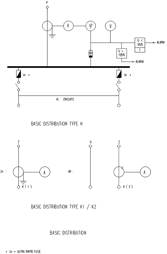
Instrumentation and relays shall be provided according the setup resulting from the schematics attached to this specification and as given in the requisition.
4.12 Alarms
Vendor shall provide an alarm system to enable purchaser to make the necessary correction in order to ensure a safe power supply. Alarm system shall be of the first failure type (first blinking remaining steady).
Alarm lights shall be executed in red signal lights with durably engraved nameplates (white surface with black engraving).
Vendor shall group all individual alarms on a relay such that one external alarm is available on a potential free changeover contact, contact rating 110V DC 1 amp.
Alarm system shall be proved with a common reset and a test push button for all signal lights.
Lamp holders of alarm and signal lights shall be made of heat resistant material. Lenses shall be made such that signals are visible from aside.
|
Alarms required (minimum) |
||
|
Indication |
Alarm |
Signal only |
|
Input AC failure rectifier |
X |
|
|
Input AC failure stand-by supply |
X |
|
|
AC present rectifier |
X green neon |
|
|
AC present stand-by supply |
X green neon |
|
|
Over current AC rectifier |
X |
|
|
Over temperature rectifier |
X |
|
|
Earth fault DC |
X |
|
|
Over voltage DC |
X |
|
|
Under voltage DC |
X |
|
|
Inverter: On |
X green neon |
|
|
Inverter overloaded |
X |
|
|
Over temperature inverter |
X |
|
|
Battery circuit breaker closed |
X green neon |
|
|
Changeover: |
||
|
Supply from inverter |
X green neon |
|
|
Supply from stand-by |
X yellow neon |
|
|
Standby supply main fuse blown |
X |
|
|
Over temperature static |
X |
|
|
Changeover |
X |
|
|
Output under voltage |
X |
|
|
Output over voltage |
X |
|
|
Back transfer to inverter supply |
||
|
blocked manually |
X |
|
|
Synchronizing indicator |
X white neon |
|
|
Control switches out-off |
||
|
Auto-position |
X |
Note: Vendor shall be provide a bypass switch over the outgoing alarm contact.
4.13 Measurement
The following measuring instruments shall be provided:
1 DC voltmeter for rectifier output voltage
1 DC ammeter with zero centre scale, for battery current
1 AC voltmeter with selection switch - inverter/load/stand-by supply
1 AC ammeter for UPS output current.
4.14 AC Distribution Board
4.14.1 The AC distribution board shall consist of:
- Main load break switch
- Outgoing circuits, switches and slow type fuses
For sizes of switched and fuses see diagram attached to requisition.
4.14.2 All outgoing circuits shall be provided with terminals to connect outgoing feeder cables plus 10% spare terminals.
4.15 Spare Parts
Vendor shall provide together with the quotation a separate list of spare parts required for start-up and normal operation (five years).
List shall contain amongst others:
Power semiconductors, print modules etc.
Spare parts shall be part of the quotation and will be part of the order.
4.16 Service Manuals
Vendor shall provide service manuals, in the quantity as required in the requisition. Supply of the service manuals:
one copy with equipment remaining copies to purchaser.
Service manual shall contain:
Factory test reports
Oscillographs
Schematic diagrams
Trouble shooting guide with waveforms and voltages
Print module layouts with component indication
Components list
Service manual shall be laid out such to enable the electronic plant service engineer with basic equipment (oscilloscope) to locate faults and replace components, as well as adjust controls, by giving pulse shapes, etc.
Service manual shall contain the fuse caracteristics of all fuses applied.
4.17 Modes of Operation
4.17.1 Normal Mode
The rectifier derives power from the input AC line and supplies DC power to the inverter, while simultaneously maintaining the battery fully charged. The load is powered by the inverter thought the static switch.
4.17.2 Emergency Mode
The input AC line has failed, the rectifier is inoperative and the battery supplies DC power to the inverter. Output voltage of the inverter remains within the specified regulation and total harmonic distortion limits during this mode.
Upon return of mains supply or in case the UPS is powered from and emergency source of power which will be available within a very short time the rectifier supplies DC power to the inverter again while simultaneously recharging the battery. If the battery has been heavily discharged the rectifier shall automatically switch to boost charge for a predetermined time.
4.17.3 UPS Malfunction or Overload
The static transfer switch shall automatically switch the load to an alternative supply or to the incoming mains. The static transfer switch shall never permitted to changeover in either direction unless both sources are synchonized and phase locked with each other.
When the load and the UPS return to the normal operating range the static switch shall automatically retransfer the load back to the inverter.
4.17.4 Bypass Mode
In order to maintain an uninterrupted supply to the load during maintenance it shall be possible to bypass both the inverter and the static switch and supply the load directly from the stand-by supply. Isolating switches shall be supplied to enable safe service operations.
Maintenance and/or repair will be possible when relevant parts of the panel will be isolated from the supply and the outgoing circuits.
The set-up of UPS shall be such that for service and adjustment purposes only, the prevailing position of the changeover switch for the UPS supply can be locked out, such that only after the service is carried out, the automatic changeover will go to the prevailing UPS position.
Fault location should be done as indicated in the service manual e.g. by replacing of print modules. The inverter shall be started anually and only in case of a healthy supply automatic changeover shall follow.
The control of the rectifier, inverter, change over and stand-by supply shall be done by means of key controled switches. Isolating switches, adjustment controls, outgoing circuits etc. shall be mounted inside the panel to avoid misoperation
Notes:
-
Keep battery well maintained.
-
Perform regular functional check as described in the service manual e.g. changeover operations etc.

