Table of Contents
The purpose of this procedure is to define the division of responsibility between Control Systems and Process Department for data handling in such a way that it can be audited.
The data exchange shall be used for the determination of type and size of instrumentation for the following categories.
1.1 Instrumentation which is Part of Plant Safety Systems
As follows:
- relief devices (relief valves, rupture discs etc.)
- actuating devices (on/off valves, control valves)- initiating devices (analyzers, flow, level, pressure, temp. etc.).
1.2 Instrumentation which is Part of Regulatory Measurement and Control
As follows:
- analyzers
- flow measurement devices
- level measurement devices
- pressure measurement devices
- temperature measurement devices
- control valves
- on/off valves
- miscellaneous measurement devices.
It is the intention of this procedure to establish the basis for the division of responsibilities between the Control Systems and Process task force groups.
This procedure defines the collection of data, data handling and the presentation of the required process data for the selection and/or sizing of instrumentation, control and safety devices.
The work division shall be followed on all projects.
It must be appreciated that there are aspects that cannot be defined or foreseen, such items shall be resolved by mutual agreement between the Control Systems and Process Task Force Group which shall be confirmed in writing.
It is considered essential that close cooperation and coordination is maintained between the Control Systems and the Process Task Force Group.
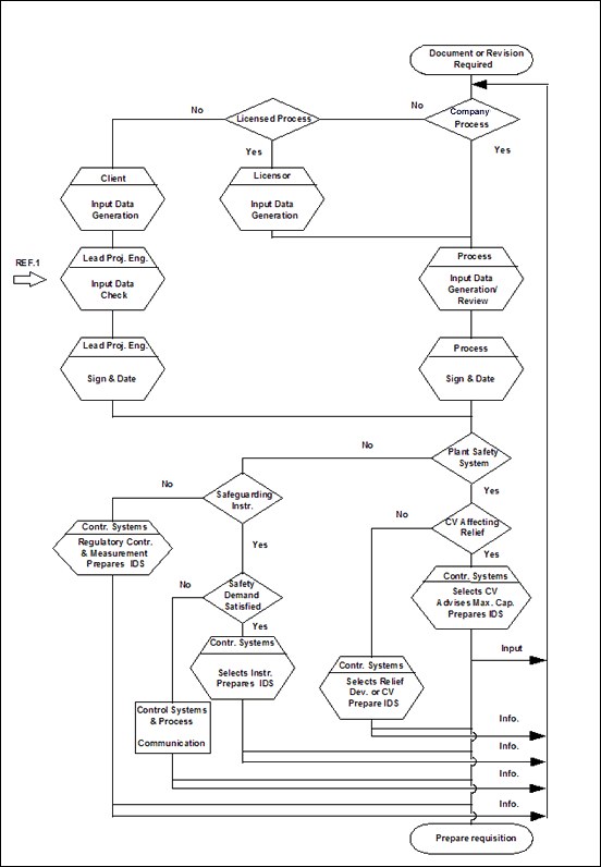
3.1 Process Engineering Group
The Lead Process Engineer shall be responsible for the quality and timely availability of the required process data.
3.1.1 Instrumentation for Plant Safety Systems
1. Relief Devices
The Process Engineer shall be responsible for determining the relief loads for the applicable cases of all the relief devices.
The following data shall be submitted by the Process Engineer to the Control Systems Engineer:
- relief loads
- process fluid physical properties under operating conditions
- special considerations which may affect the selection and/or the sizing of the relief devices.
2. Safeguarding Instrumentation
The Process Engineer shall be responsible for submitting the following data to the Control Systems Engineer:
- requirements for reliability of the device with respect to the safety requirements
- physical properties of the process fluid under operating conditions trip settings
- trip settings
- conditions for sizing of instrument equipment (design pressure, throughput min/max/oper., allowable pressure drop etc.)
- special considerations which may affect the selection and/or the sizing of the instrument devices.
3.1.2 Instrumentation for Regulatory Control and Measurement
The Process Engineer shall provide the following data to the Control Systems Engineer:
- physical properties of the process fluid under operating conditions
- throughput ranges min/max/oper.
- dP (allowable pressure drop)
- pressure settings/pressure ranges
- alarm settings
- design pressure
- levels
- interface levels
- temperatures
- requirements for analysis and accuracy of analysis
- special considerations which may affect the sizing and/or the selection of instrument equipment.
3.2 Licensed Processes
In case of a Licensed Process, the required process data shall be obtained via the Process Engineer who is responsible for the coordination.
3.3 Projects Where Company has no Process Design Responsibility
In case Company has no process design responsibility the required process data shall be obtained from the Client via the Lead Project Engineer.
The Lead Project Engineer shall consult a Process Specialist, as per an arrangement defined in the PPEM, for checking the data. The Lead Project Engineer approves and dates the transmittal of the data to Control Systems.
3.4 Control Systems Group
3.4.1 Instrumentation for Plant Safety Systems
1. Relief Devices
The Control Systems Engineer shall be responsible for the following:
- providing information about control valves affecting the relief valve size
- preparing an instrument data sheet (Company or Client standard data sheet)
- calculating the size of the relief device based on the applicable sizing code
- after selection of the relief device and completion of the instrument data sheet the Control Systems Engineer shall issue the data sheet to the Process Engineer for information.
2. Safeguarding Instrumentation
The Control Systems Engineer shall be responsible for the following:
- preparing instrument data sheets (Company or Client standard data sheet)
- performing calculations where applicable for flow devices, control valves, etc.
- selecting an instrument which complies with the process demand for safety to perform its function as specified.
If safety demands cannot be met then the Control Systems Engineer shall work out a suitable alternative in cooperation with the Process Engineer.
- after selection of the instrument and completion of the instrument data sheet the Control Systems Engineer shall issue the data sheet to the Process Engineer for information.
3.4.2 Instrumentation for Regulatory Control and Measurement
The Control Systems Engineer shall be responsible for the following:
- preparing instrument data sheets (Company or Client standard data sheet)
- performing calculations where applicable for flow devices, control valves, analyzer sample lines etc.)
- selecting a suitable instrument
- after selection of the instrument and completion of the instrument data sheet the Control Systems Engineer shall issue the data sheet to the Process Engineer for information.
4.1 Units of Measurement
Units of measurement of a project shall be as per the PPEM for process data transfer.
Units of measurement not covered in the PPEM shall be mutually agreed between the Control Systems and Process Task Force Group and confirmed in writing.
4.2 IDFS (Instrument Data Flow Scheme)
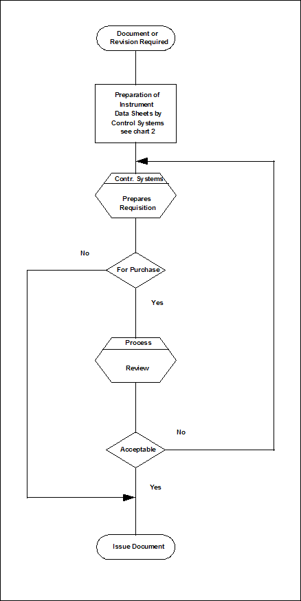
At the beginning of a project the Control Systems Engineer on the project task force shall set up the IDFS based on the P&ID's.
The Control Systems Engineer shall assign identifier points on streams where process data are required.
When all instrument identifiers are assigned on the IDFS these shall be numbered and issued internally within the project task force.
If at a later stage process data are required for additional or modified instrumentation due to developments, the Control Systems Engineer shall mark-up the relevant IDFS.
4.3 IDS (Instrument Data Sheets)
The Control Systems Engineer shall prepare/issue instrument data sheet forms containing the identifier points.
Alternatively line/equipment numbers from P&ID's and the instrument tag number shall be used.
The IDS shall be the Client's or the Company standard forms (examples, see attachments).
The Process Engineer shall mark-up the required data and return the IDS dated and signed to the Control Systems Engineer.
Before the purchase issue of the requisition the IDS's shall be issued internally by the Control Systems Engineer for final verification by the Process Engineer.
4.4 Process Data Transfer by Means of SQL Table or DATABASE Files
In case the project task force set up is such that both the Process and Control Systems Departments are working with SQL tables and/or DATABASE files (multi discipline use of SQL data tables or DATABASE files) then the Process Engineer shall input the required process data (with the relevant stream condition points and stream numbers if applicable).
In parallel the Process Engineer shall internally issue a printed copy which shall be dated and signed in such a way that it can be audited.
The Control Systems Engineer shall download the file into his own data file for further use.
The Control Systems Engineer shall verify the downloaded data against the printed copy from the Process Engineer.
In case of SQL table or database revision by the Process Engineer only the relevant sections shall be internally distributed on hard copy, dated and signed.


Project Procedure and Execution Manual (PPEM)
- BN-K071 : Design Data Flow Instruments
- BN-K073 : Design Data Pressure and Temperature Instruments
- BN-K074 : Design Data Analyzers
- BN-K075 : Design Data Safety Devices

