Table of Contents
- Thermowells
- Level Instruments
- Selection of Type of Connections
- Minimum Clearances for Instrument Connections:
- Tank Gauge
- Typical Examples
1. Thermowells
1.1 Thermowells in Distilling Columns
1.1.1 Location of Thermowells
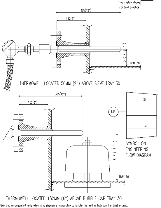
According to Company practice, thermowells are located two (2) inches above the tray, but not in the downcomer.
Although the location of a thermowell in the downcomer provides a better heat transfer, even with column loading down to 1/3 of design capacity the possibility of a flooded tray, caused by the restriction of the thermowell, when located in the downcomer, dictates the Company policy to install the well above the tray. The location of the well, 2” above the tray, normally proves to provide adequate beat transfer at column loadings down to approx. half of design capacity, because in the range of these column loadings the liquid on the tray is forming a foamlayer, which is sufficiently high to contact the well.
However, in absorbers for example, the Process Department normally prefers to measure the vapour temperature only, (this vapour temperature being noticably different from the liquid on the same tray). The well should be in this case located for example 2” below the next tray in the vapour space (check this requirement with Process Department).
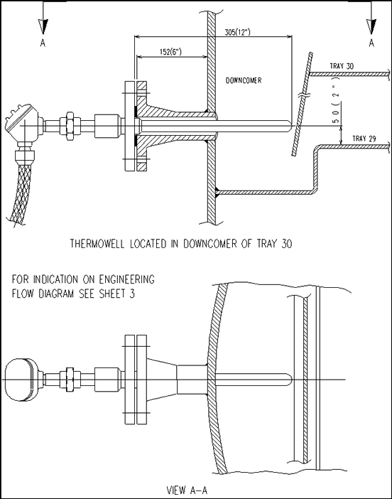
When for one or another reason the well is located in the downcomer, this might be indicated by the statement: “locate in downcomer of tray 12”. In this case the thermowell shall be located two (2) inches above tray 11 in the downcomer or tray 12.
Thermowells are normally mounted 90° to the wall of the tower.
In accordance with Company practice we will not normally install thermowells under an angle.
Reference is made to sketches on sheets 4 and 5.
Check that immersion of thermowell is sufficient.
Obtain from the Vessel Department the normal nozzle stand-out, used for the particular project.
Normally the nozzle stand-out is 150 mm.
Select the nearest standard immersion lengths for the thermowell.
However, extra long immersion lengths are required in case wells are destined for filled system temperature bulbs.
Check for clearance of thermowell (inside/outside vessel).
Because Piping Department will orientate the well, it is important that the Vessel Department and the Piping Department take into account the selected immersion length in order to avoid the thermowell interfering with the downcomer, valve tray, bubble cap or any other tower internal.
The Vessel Department shall further check that the elevation of the thermowell is not interfering with the weld of the tray or with any other (plate-) weld of the tower involved.
The latter check will be done when vendor’s prints are received by the Vessel Department.
Check also that thermowells can be easily withdrawn from vessel without interfering with manholes and other equipment, such as ladders, railings, etc.
Standard clearance required for normal application: 600 mm.
When a thermowell in a tower has to be relocated up or down due to impractical orientation with regard to platform or ladder, the Piping Department shall contact the instrument engineer.
The instrument engineer in his turn will in coordination with the Process Department check for a possible relocation of the particular thermowell in the next higher or lower tray so permitting a 180° reorientation.
1.2 Thermowells in Heat Exchangers
Do not install thermowells in heat exchanger nozzles.
The connection provided as a standard by heat exchanger manufactures remain plugged-off and shall not normally be used for thermowells.
The thermowell shall be located in the pipe rather than in the heat exchanger nozzle, because:
-
The heat exchanger drawing has not to be sent to the Instrument Department for checking, thus reducing the amount of paperwork.
-
In many cases the heat exchanger nozzle diameter is not sufficient to accept the thermowells with the required immersion length. (For standard wells nozzle 4”.)
-
In case thermowell connections are flanged, the flange of the thermowell connection will interfere with the flange of the heat exchanger nozzle.
An exception to the rule might be in case temperature has to be measured in between stacked heat exchangers.
In this case it will be too expensive to provide for short extensions between the stacked heat exchangers to receive the thermowell connections.
This is especially true for stainless steel equipment.
Another exception made for the thermowell shown on the flowsheet as located between block valve and heat exchanger.
If this location is required due to process reasons, the well should preferable be located in the heat exchanger nozzle rather than providing a spool piece.
1.3 Thermowells in Drums, Storage Vessels, etc.
In general, reference is made to the notes above, as far as applicable.
The immersion length shall be carefully selected and must not be taken too short, as otherwise no exact temperature measurement can be made.
For flanged thermowells do not use smaller nozzle sizes than 11/2”, because I.D. of the nozzle will interfere with O.D. of well. Especially at flange facing end, the weld of the thermowell at the thermowell flange will interfere with the nozzle I.D. at the nozzle flange face.
When the well has a too long immersion length and especially when a particular vessel or storage tank is provided with a mixer, one should investigate, whether a 2 inch flanged thermowell, instead of a 11/2 inch flanged or 3/4 inch screwed thermowell can be used.
Thermowells in spheres, located in the liquid (bottom side), should be positioned horizontally in case nozzles are flanged. This will avoid accumulation of water in this particular nozzle so to avoid danger of freezing as there is always the possibility that water will settle out in a vertical located nozzle in the bottom.
1.4 Thermowells in Reactors
Reference is made to the various design notes, listed above as far as applicable.
In case very long reactor thermowells are used, one should carefully check the necessity for further bracing of the thermowell.
It is our practice in these cases to have the thermowell delivered by the vessel manufacturer, in order to obtain optimum construction.
For reactors with a fluidized bed, special internal protecting sleeves might be required to protect the well against the abrasive action of the catalyst.
Reactor filled with catalyst might require special thermowells with a tapered tip to permit insertion of the well into the catalyst bed.
When a so called multiple point reactor thermowell is used, a special “larger” diameter well is required for inserting the various reactor thermocouples with spring devices.
1.5 Accuracy of Dimension to Tangent Line, etc.
It is important that the vessel manufacturer will understand our requirements, see BNS-1003.
Due to tolerances in vendor’s shop when indicating nozzle connection on plate, the thermowell connection might be put a little bit too low and will then interfere with the weld of the tray.
Therefore dimensions are to be given related to tray level, rather than related to tangent line, so as to decrease the possibility of measuring errors in the shop.
Another important point is that the thermowell connection in mounted exactly 90° to the towerwall, because otherwise the tip of the thermowell might interfere with the tray.
2. Level Instruments
2.1 Level Glasses
2.1.1 General
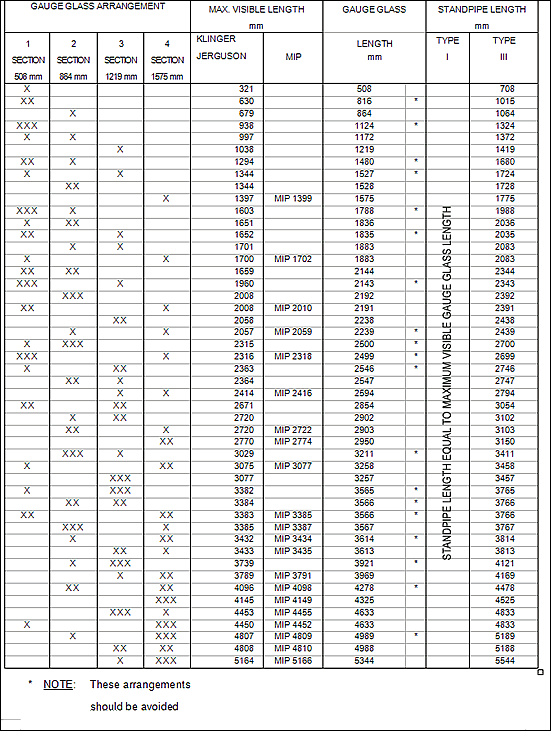
In accordance with Company standard practice, level glasses with up to four (4) glasses, size number nine (9) are used. (For clarification see sheet 28.) A larger size than the four times size number 9 shall not be used, because the weight of such a level glass becomes excessive, especially with regard to the 3/4 inch vessel connection size.
Some clients even prefer not to install level glasses with more than 3 times size number 9 glasses.
If a longer range is required, a combination of the various sizes level glasses can be used, see table on sheet 27 and 28.
In this arrangement with 200 mm overlap of the vessel connections the overlap of the visible range is about 14 to 20 mm (depending upon gauge glass model).
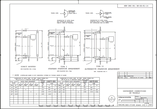
It is advisible that when more than 2 level glasses are required, a standpipe is used in order to avoid too many connections on the vessel itself (see item 2.4.)
On interface service, however, the level glasses shall preferably be direct mounted to the vessel and standpipes shall be avoided.
In some isolated cases special level glasses with a center (middle) tapping are used for interface.
For “pad” type level glasses the glass size “no. 9” should also be selected to reduce spare parts.
The visible range of level glasses is selected according to the following policy:
-
The level controller range, if any, shall be overlapped.
-
(Preferably 10 mm at each end.)
-
The low or high level alarms shall be overlapped.
-
Low or high operating levels shall be covered.
Note: Sometimes overlapping of the complete level controller cannot be achieved. This is especially true for level controllers, located on a boot. In this case preferably 10% and 90% of the level controller range shall be visible in the gauge glass. For extremely long levels it might be sufficient to provide glasses at the upper, middle and lower part of the vessel (in this case overall level glasses).
2.2 Level Controllers and Alarm Devices
2.2.1 General
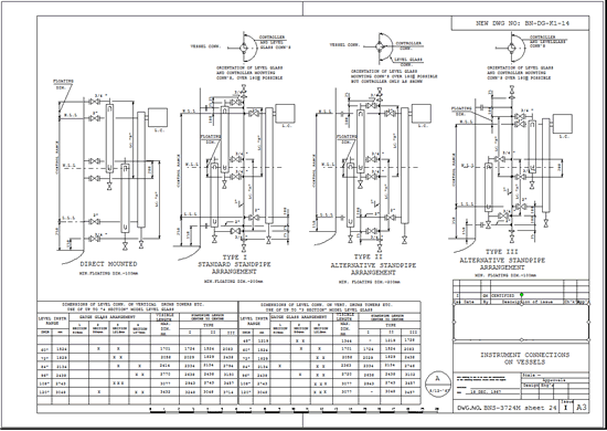
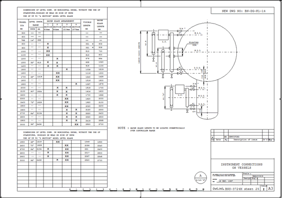
Reference is made to the sketches and table on sheets 23 thru 26 for the recommended elevations of level alarms, level controllers, gauge glasses, etc.
In accordance with Company standard practice, external displacers shall be used up to 60 inches, for larger ranges d/p cells shall be used.
However, one might consider the use d/p cells on stainless steel vessels in smaller ranges for economical reasons.
In all cases an accurate check is to be made whether the d/p cell is suitable for the application involved (wet leg, dry leg conditions).
If possible d/p cell instruments shall have ranges equal to external level displacers so that one might interchange this type of equipment with each other, wherever required.
2.2.2 External Displacers
External displacers can be used for most applications including interface.
The side-side connection is normally used because this will permit a level glass/level controller arrangement with the lowest control level. Also additional piping work is reduced to a minimum.
2.2.3 Internal Displacers
2.2.3.1 Level alarms with ball floats or spherical floats. These ball floats or spherical floats shall not interfere with the inside diameter of the nozzle. Level alarms with spherical floats are normally purchased in order to avoid any interference with the inside diameter of the nozzle as much as possible. Special attention should be paid in case due to corrosion allowance the nozzle has a rather heavy schedule (wall thickness).
2.2.3.2 Side mounted internal displacers. These instruments are very difficult to install. Therefore one should make a large scale drawing and the instrument department will then check the following:
-
Possibility to install or to withdraw the float; also that the float with floatroad can be easily attached to the torque tube hanger assembly.
-
The exact size of the float length & floatroad.
-
The design of the stilling tube, if required.
-
That float is free from all internals of the tower/vessel.
-
In case the float is lost, the possibility to recover the float through a manhole or any other nozzle.
-
The possible requirement for a floatstop for displacers used in interface applications; because weight of float might be too large for the torquetube.
2.2.3.3 Top mounted internal displacers.
The same requirements as listed for the side mounted internal displacers apply. Once again a large scale drawing is required in order to make sure that the displacer float is not interfering with in case of distillation columns bubble caps, etc.; or in case of drums with vertical baffles or with any vessel part.
2.2.3.4 Stilling Well/Guiding Ring.
To dampen-out too violent liquid disturbance, a stilling pipe should be installed, as a standard feature, around floats of internal level controllers.
Internal side nozzle mounted ball float level alarm devices do not normally require this feature.
The internal diameter of the stilling tube should allow for at least 11 mm clearance around the float.
Normally the stilling tube diameter might equal the internal displacer nozzle size.
In some cases an upper and lower guiding ring might be used instead of a stilling tube.
The bottom of the stilling tube shall be fitted with cross bars to permit recapturing of the float when it is accidentally lost from the torque tube hanger.
The standpipe shall be provided with some venting holes in the upper part; other “equalizing” holes are in principal not required. (For exception see item 5, sheet 20.)
2.2.4 Calming Baffle
Internal bevels at level gauge, controller or standpipe connections are required wherever the impingment of inflowing process streams or reboiler outlets might interfere with the proper level instrument operation.
As a rule of thumb a bevel shall be provided when the nozzles causing impingment are located at the same elevation as the level connection.
However, these bevels should not be provided when purge or dip pipes are inserted into level nozzles.
2.3 High Temperature Applications
In high temperature service, the possible expansion of the vessel might cause the center-to-center of the nozzle connections to change, thus causing excessive strain on the level equipment, mounted on these nozzles, which due to lower temperature is not subjected to same expansion.
This is especially dangerous for level glasses.
The location of the vessel nozzles is also very important.
For example flange facing of nozzles on a front of a horizontal drum might no longer be in the same plane at high temperatures.
Some solutions to overcome this problem somewhat are:
-
Make level ranges of controllers/level glasses small.
-
Provide for extra long connection piping (or pigtail type extensions) between vessel nozzle and instrument equipment.
2.4 Standpipes
Standpipes will be applied in general for the following applications: (This is a guidance only, not a law.)
-
Where a modifications of the level arrangement or addition of extra level devices might be expected, the standpipe might provide the required flexibility.
-
Where a concentration of several level instruments around a standpipe will provide a better piping hook-up.
(This might provide better visibility of both level glass and level controller or improve accessibility to the individual instruments.)
Where Piping Department initiates the requirement for a standpipe arrangement to enable a better piping hook-up the Instrument Department should be informed, as other gauge glass sizes, etc., might be required. -
On horizontal drum, where top and bottom vessel connections are required to obtain visibility of the complete vessel span.
-
The standpipe will consist of a vertical 3 inch pipe with 2 inch branch connection to vessel. (See sketch on sh. 23, 24, 26).
The standpipe will not be separated by block valves from the vessel.
This arrangement is suitable for ratings up to 300 lbs, for higher ratings reinforcement of branch connections or the use of weldolets shall be considered, or increased standpipe size.
In all cases the standpipe construction shall be designed in accordance with the piping specification of the project involved and conform to all local code requirements.
In case the standpipe is completely filled with a liquid (interface applications) a 3/4 inch vent connection shall be provided at the top.
Further in some projects it might be desirable to have in all cases a vent on top of the standpipe to permit venting of any “air” in upper dead part of the standpipe.
Because the standpipe is not self draining into the vessel a 3/4 inch valved drain connection shall be provided at the bottom.
The standpipe shall be supported in case three or more level apparatus (level glass or external cage type) are located on one standpipe, or when the standpipe is rather long.
When a long standpipe, connected to a “hot” vessel, contrary to our practice is provided with block valves, one should investigate the possible excessive strain, which will occur when standpipe is blocked-off from vessel and cools down to ambient temperature, while vessel remains hot.
2.5 Bottom Connections
In general for “vertical” towers/vessels the bottom connection shall be avoided because the nozzle has to be extended thru the skirt.
A disadvantage of a bottom connection is the possibility of water accumulation in this lower branch and the subsequent danger of freezing and plugging.
Water might always be present - during construction due to hydrostatic testing or during operation because of water being in the products/feed stock.
When using a bottom connection, the nozzle shall extend approximately 3 inches inside the vessel to avoid the dirt/mud accumulation on the bottom of the vessel to enter into the connection.
2.6 Accuracy of Dimension to Tangent Line
Identical to item 1.5. dimensions should be indicated in a certain way. See BNS-1003.
Show center-to-center dimensions rather than dimensions from tangent line or vessel center-line.
The dimensions between center lines of level glass connections shall be very accurate, because otherwise strain might cause glass breakage of the level glasses.
Therefore the center-to-center dimension is to be indicated rather than showing these two nozzle elevations from tangent line, center of vessel etc.
In this respect level glasses with flanged connections can tolerate a bigger difference between actual center-to-center dimension and theoretical required center-to-center dimensions than screwed level glasses.
In case an inspection report mentions that the actual center-to-center line is not in accordance with the theoretical dimension one might consider to have the level glass modified in the field to exactly match the actual vessel center-to-center dimension.
This can be done by shortening the two nipples on top and bottom of the level glass.
The level gauge connection on the equipment shall be exactly 90° to the vessel wall.
In case connections are flanged, they shall be accurately in the same plane.
2.7 Design Basis for Dimensions of Level Connections on Vertical Drums, Towers, etc., as Shown on Sheet 23
2.7.1 The level controller range is used as basis for this table, using the standard vessel connection dimension of an external displacer. (See also item 2.2.1. for d/p cell ranges.)
2.7.2 The required level glass combination is selected such that:
- 0% and 100% of the controller range is overlapped.
-
At least the minimum overlap between gauge (i.e. 200 mm of the level gauge connections) is used, to obtain uninterrupted visibility.
-
Taking into account the dimension of the standpipe and/or the prescribed minimum clearance for instrument connections.
2.7.4 In case a very low liquid level reference line in specified on the process sketch, one should check whether this requirement is really valid.
This requirement might be predicted for example by process reasons on a high vacuum tower to avoid coking, but in many cases the indication on process vessel sketch for the level as “min.” is questionable.
However, the control level and/or lowest visible level in gauge glasses can be lowered by using arrangement type II, sheet 23 and 24.
2.7.5 To avoid too much weakening of the 3” pipe when the two 2” branch connections are located too close of reinforcement and/or weldolets shall be considered.
Design to be checked against pipe specification and local codes.
2.7.6 Do not locate the lowest visible level of a gauge glass below the lowest 2” standpipe branch connection to the vessel as to avoid false level indication.
This also applies to upper visibility of a level gauge glass on a standpipe.
2.8 Design Basis for Dimension of Level Connection on Horizontal Drums as Shown on Sheet 25 and 26
2.8.1 The vessel diameter is used as basis for this table.
2.8.2 From this vessel diameter the maximum possible level control range is determined using the standard vessel connection dimension of an external displacer.
2.8.3 The required level glass combination is selected such that:
-
and 100% of the controller range is overlapped.
-
At least the minimum overlap between gauges (i.e. 200 mm of the level gauge connections) is used, to obtain visibility.
-
Taking into account the dimension of the standpipe and/or the prescribed minimum clearance for instrument connections.
Notes:
- For horizontal drums, the maximum visibility which is possible with the gauge glass combination is selected.
- Items b and/or c apply, whichever is the governing factor.
2.9 Design Basis for Dimensions of Level Connections for Various Level Gauge Combinations, as Shown on Sheet 27
2.9.1 This table shows the various combinations of level glasses and also the minimum dimensions for a standpipe to be used for this combination.
2.9.2 It should be noted that a combination of, for example two “three sections” level glasses is cheaper than the combination of three level glasses (i.e. two items “one section” plus one item “four sections”), because extra block valves and additional piping influences the price considerably.
3. Selection of Type of Connections
The selection of a flanged, socket weld or screwed type of connection for instruments, is, in many cases determined by the client.
Basically these vessel connections will follow the piping specification.
In Europe the vessels are normally flanged because continental screw threads are not reliable (parallel threads) and socket welded connections are not very well known or not available for DIN piping.
The disadvantage of a screwed connection on a vessel is in case of damage to the threading.
In case of damage to the screwed connection in most cases the boss has to be replaced, requiring also that the vessel has to be made gas free.
Making vessels gas free is a rather clumsy and difficult operation.
The same argument applies in the case of a socket weld connection because the block valve cannot be removed for replacement.
For this reason flanged connections are more frequently used, especially in chemical plants.
Sometimes those parts of equipment which can be easily dismantled and moved outside the plant area might still have screwed/socket weld connections (for example heat exchangers heads).
Please note that it might be advisible to use stainless steel nipples with teflon packing for attaching block valves to screwed instrument connections, even in carbon steel classes, to avoid binding of the nipple.
Spheres should preferably be flanged rather than screwed because of the potential hazard of the large amount of hydrocarbon liquid in the sphere when screwed connection starts leaking.
Thermowells shall not be welded into the equipment but either screwed or flanged.
Breather valves, flame arrestors, gauge hatches and other cast aluminium or cast iron equipment require nozzles with flat facing.
4. Minimum Clearances for Instrument Connections:
Minimum clearance for instrument connections of 2” and smaller from tangent lines, welding seams, etc. on vessels are given below.
These clearances are based on some general accepted piping guidance for unfired pressure vessels.
The Vessel Department will check our assumptions for these clearance with local codes - for example for the French code: “C” becomes: 50 mm + 1/2 nozzle dia.
|
TYPE - A |

|
Use A = 6” if vessel has a wall thickness of 1/2” or less, or 8” if vessel has a wall thickness more than 1/2”. |
|||
| TYPE - B | 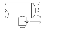 |
Use B = 6” if major drum has a wall thickness of 1” or less. |
|||
| TYPE - C | 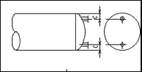 |
C = Minimum distance to inside circumference. Use C = 6” if vessel has a wall thickness of 1” or less and diameter 36” to 144”. |
|||
| TYPE - D | 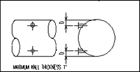 |
D = Minimum distance to inside circumference for 600 LBS flanges and below. Use for “D” dimension in general 150 mm (6”), in critical cases follow table below. |
|||
|
VESSEL DIAMETER |
24-60 IN. |
60 IN.-UP
|
|||
|
D for 1” conn. D for 11/2” conn. D for 2” conn. |
4 41/2 43/4 |
5 51/2 53/4
|
|||
When designing standpipes or designing the process piping around external level float cages, note that a minimum of 2 inch is preferable required between O.D. to O.D. of connections.
This figure is effected by requirements of local codes.
5. Tank Gauge
Tank gauge equipment requires special attention, because the various makes have different dimension and nozzle sizes.
Further some models have non-standard (11/4”) size screwed or flanged connections. When flanged connections are used watch interference of these flanges.
For bide issue of tank requisition the dimension/sizes are often based on a certain make, and need to be modified as soon as the vendor is known.
The tank gauges normally require three nozzles - two nozzles for spring housings with float guide wires and one nozzle for the tape. Do locate nozzles as shown on sketch, otherwise the spring housing might interfere with the tape conduit.
Observe manufacturer’s recommendation for min. distance to tank wall and minimum required size of manhole to enter the float into the tank.
When tank is provided with a liner the guide wire anchor bar should be made of a corrosion resistant material and be installed/delivered by tank vendor.
Some tank gauges require stilling pipes which should be supported with a bracket from the tank wall near the bottom of the tank to obtain maximum accuracy of level measurement even when tank roof is setting, in case tank is filled.
The stilling tube for these tank gauges require a great number of equalizing holes as otherwise a false rise of liquid level inside the stilling pipe might occur, causing false float readings.
Floating roof tanks require special engineering.
Sometimes a swimming pool measurement is made, sometimes float is located in the floating roof guid pole.
The temperature measuring device associated with automatic tank gauge comes in two forms.
-
Spot temperature by means of an ordinary thermowell in the tank wall.
-
Average temperature by means of a multi sensing element device, housed in vertically installed thermowell.
In floating roof tanks this well is to be properly protected against damage when roof is moving up and down.
Some average temperature devices consist of a spiral, attached to the roof and bottom; this requires a special check, as to whether the spiral element can be brought thru the manhole.
Another type average temperature device is attached to the float and tank roof and requires some extra sheaves.
It is Company’s practice to have either the tank vendor or the gauge vendor (in coordination with tank vendor) supplying the stilling tube.
Further, the gauge installation shall be contracted (if possible depending facilities of gauge vendor for the country of construction involved) with the gauge manufacturers who should be instructed to cooperate with the tank vendor.
In all cases the gauge supplier shall approve the actual tank prints for the gauges connections/installation.
6. Typical Examples
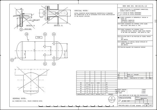
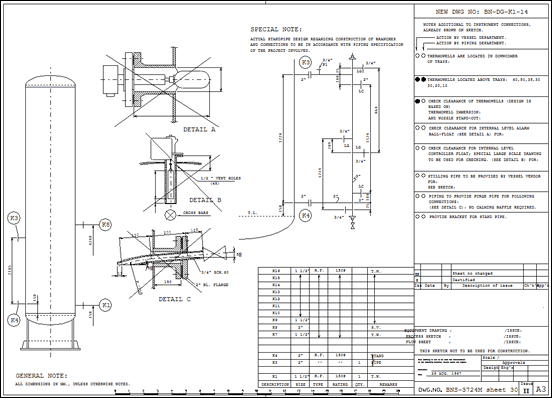
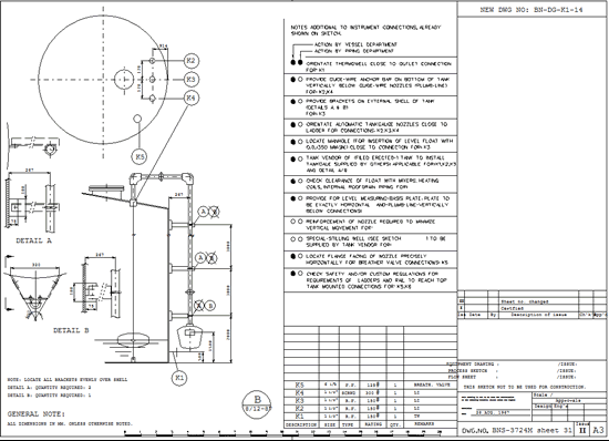
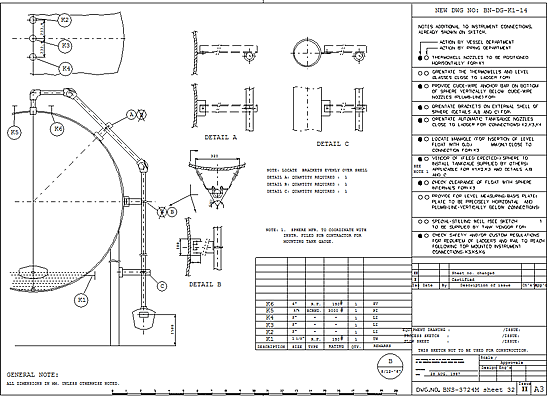
On sheet 29 thru 32 typical “marked-up” instrument vessel sketches are showing the application of the various design notes given in this standard.
In case the official vessel drawings are not yet issued with instrument nozzle (tag) numbers, the nozzles shall be numbered in the following sequence:
-
for vertical vessels/towers from bottom to top.
-
for horizontal vessels from left to right.
-
normally each nozzle has a separate number, except for equipment (such as reactors) with a large number of nozzles; in this case all nozzles for the same instrument or the same type of instrument will bear the same number.
 |
|||
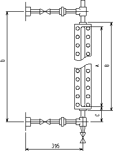
| 1 | In accordance with Company standard practice gauge glasses with standard gauge glass size "no.9" (nominal 320 mm visible length) are used to minimize spare parts. | ||
| 2 |
If possible provide approximate 1000 mm clearance on top of gauge glass to permit inside cleaning of gauge by special gauge glass cleaning brush. Allow for approximate 150 mm clearance behind gauge body for (future) illuminator. |
||
| 3 | Typical arrangement for more than on gauge glass with overlap allowance for continuous visibility. | ||
 |
|||
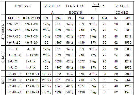
* Dimension dependent on size and manufacturer of gauge glass.
