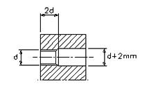
Design standard of jackscrews for girth flanges of heat exchangers. Use this standard for study purposes only.
General Notes:
- Locate the jackscrews in the boltcircle of flange bolts between two flange bolts.
- Jackscrews to be about equally space, but not located in centerlines of the exchanger
- For jackscrews see exchanger drawing
- On set of jackscrews shall be provided for each pair of main flanges. The jackscrews shall be fitted in the flange of the removable part, e.g. shellcover flange, channel flange at tubesheet side and channel cover. Except flange 3 and 4 for floating head exchangers, which need jackscrews on both flanges
- Thread to be same type as used for the flange bolts ( ANSI, Whitworth or Metric)
- Bolt threaded length to be sufficient to jack flanges apart by 25 mm
- When flange thickness does not exceed 2d or when the depth of the drilled hole does not exceed 5 mm, jackscrew hole to be threaded over full flange thickness.
| Exchanger size |
Bolt size d | Required number |
|
| ANSI and Whitworth |
Metric | ||
| 12" and down | 1/2" | M12 | 2 |
| 14" to 24" incl. | 5/8" | M16 | 3 |
| 26" and up | 3/4" | M20 | 4 |
The next figure shows a typical design:


