")
General Requirements
Table of Contents- General
- Maintenance and Safety
- Supports
- Protection against Corrosion
- Damages
- Scaffolding
- Models
- Assistance During Starting Up
- Cable and Wiring Installation
1. General
The electrical installation including provisional installation work required during erection shall conform to good working practice of high quality and safety. The requirements are intended as minimum for the electrical facilities described and none shall be deleted. However, with Engineer’s approval, requirements may be added with a view to improve safety, reliability, interchangeability, maintenance and expansion possibilities.
Installation work in areas classified as hazardous in relation to the possible escape of explosive gases or vapours shall be carried out in strict accordance with the relevant local regulations and the requirements laid down in the Electrical Area classification drawing(s). Installation work in existing plants (e.g. revamp W) may only be carried out after having obtained the necessary permits from the Chief operator of these plants.
Installations in outdoor areas shall be weatherproof in addition to the requirements imposed by a possible classification with regard to explosion danger.
Completed parts of the permanent electrical installation used by Contractor during erection period such as elevators, switchboards, lighting installations, etc, shall be handed-over “as new” to the Engineer upon termination of the work.
2. Maintenance and Safety
The electrical installation when completed shall ensure convenient operation and easy maintenance of equipment. In particular location and/or construction of cable supporting systems, control stations for electric motors, panels, lampfittings and junction boxes shall be well considered.
Locations of electrical equipment as indicated on the design drawings are approximate only and shall be determined exactly by Contractor considering above requirements and avoiding interference with mechanical equipment and pipelines.
Warning plates shall be supplied and installed by Contractor as required by law and good engineering practice.
Location of any piece of elec. equipment may not hamper maintenance to mechanical equipment.
Power outlets for maintenance shall be installed in Process and Utility areas, (in Tankage areas only in those areas where regular maintenance is required) such that every location at grade can be reached with an extension cord of 50 meters. Preferred location, at substation and in safe areas.
3. Supports
Supports for electrical equipment and cable tray systems may be mounted to structural steel or walls, however, only if approved by the Engineer.
No supports may be mounted to:
plant equipment and process piping;
fireproofed structural steelwork, however, mounting before steelwork is fireproofed will be allowed. (refer to Lignting Installation)
Breaking or cutting into acid resistant surfaces for any supporting or fixing is not permitted. If such supporting could not be avoided it has to be done by qualified civil labour.
Fixing of supports, mounting plates, etc. to structural steel may be by means of welding, shootgun or suitable clamps. When structural steel has been galvanized, only the clamping method is allowed.
Before welding is applied the surface shall be cleaned, and primed and painted with corrosion resistant paint after the welding.
All field fabricated freestanding frameworks, supports, mounting plates etc. required for lighting panels, motor control stations, relay panels, terminal boxes, cable supporting systems, etc. should have a thickness not less than 3 mm, should be properly made and mounted, should have all rough edges smoothed and need approval on the design from the Engineer prior to fabrication.
4. Protection against Corrosion
In general all field fabricated steelwork shall be hot dip galvanized after fabrication.
When approved by the Engineer steelwork may be steel blasted and provided with a coating of zinc-compound paint. Further painting shall be done by others after installation except those parts that cannot be reached.
All screws, bolts, nuts and washers shall be zinc plated. Any prefab. cable trays shall be hot dip galvanized or plastic coated (after perforation).
To prevent galvanic corrosion the use of different metals mounted together shall be avoided in wet and/or chemical atmospheres.
Wherever prefab. cable trays have been cut then the bare edges must be sealed and protected as far as possible. Zinc compound paint shall be used for hot dip galvanized trays and a liquid plastic solution or a two pack epoxy paste for plastic coated trays.
5. Damages
Immediately when equipment or material is received it shall be unpacked and thoroughly examined for possible damage which may have occured during transport. The equipment or material shall be signed for according to the result of this examination and any damage found shall be reported to the Engineer immediately.
Equipment or material damaged during installation due to rough or unskilled handling, wrong cutting of cables, or other ways of wrong handling by Contractor shall be replaced or repaired at his expense.
Equipment or material damaged by others due to failure of Contractor to apply adequate protection to it shall be replaced or repaired at Contractor’s expense.
Any damage which may occur during installation shall be reported immediately to the Engineer who will decide upon replacement or repair.
6. Scaffolding
Generally Contractor shall arrange for any scaffolding necessary to do his job. If specified, scaffolding installations will be made by others. Requests for scaffolding should be made one week in advance through the Engineer who will decide upon the necessity of these requests.
7. Models
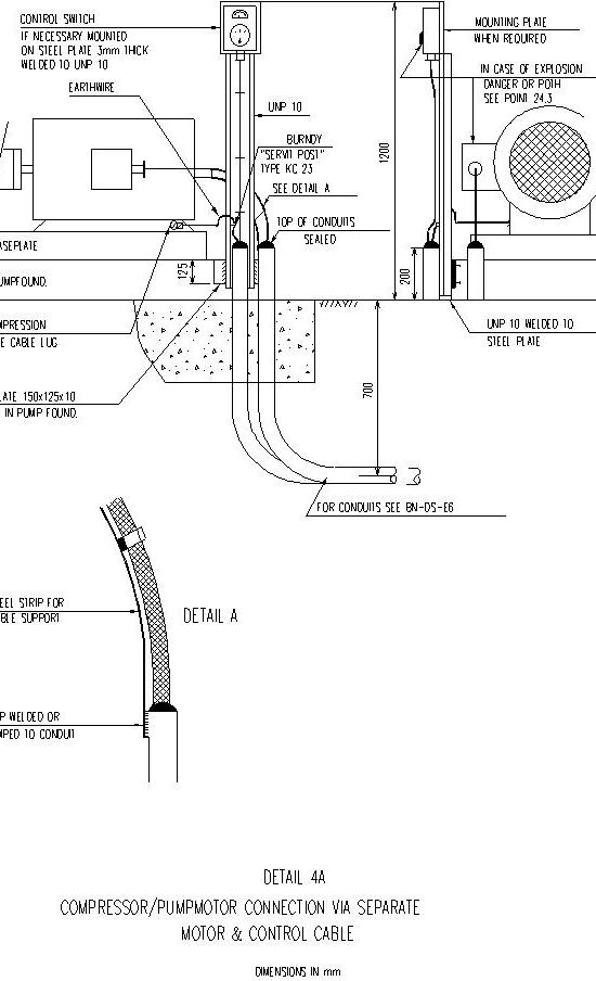
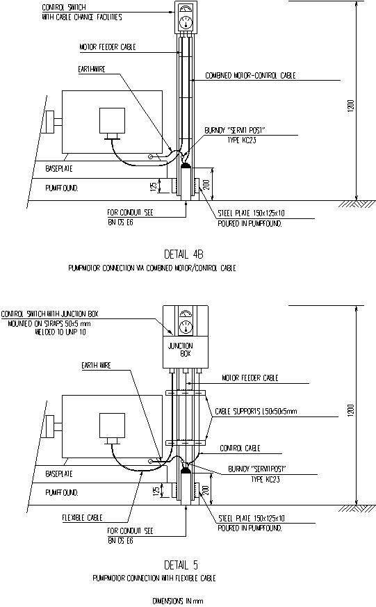
A model as an actual sized dummy shall be made by Contractor and approved by the Engineer before starting the installation of:Supports for motor control stations,
connection of cable to horizontal/vertical motors,
rising points of cables through floors (typicals),
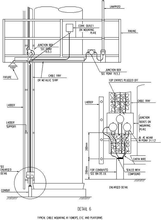
change-over points for underground to overhead cables (see below detail 6),
supports for panels (refer to Supports at this page),
cables of several size mounted on cable tray,
lampposts and convenience outlets attached to handrailings,
any mounting system that deviates from this standard.
8. Assistance During Starting Up
During starting-up of installations Contractor shall make available (on a unit-price base) a crew of electricians on a “24 hours a day” working scheme. They shall assist in correcting possible defects and/or carrying out any remedial work. The composition of this crew and the period of availability shall be determined separately for each case by Client.
9. Cable and Wiring Installation
Supporting systems
General
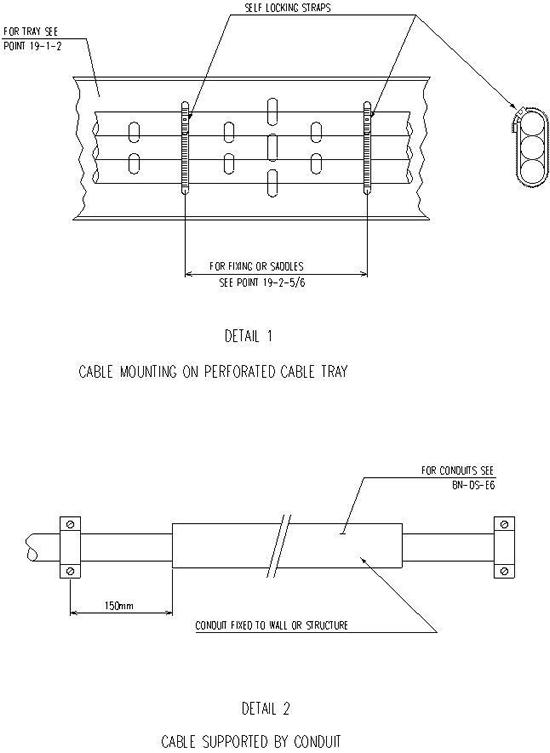
Cables shall be supported by cable trays, racks or ladders, fastened to metallic strips with self locking type straps or run through steel pipes all the way up to their termination. (see below details 1-6). These supporting systems may be common for power, lighting and control but “special” cables shall be run on separate systems. Other methods need the Engineer’s approval. Cable supports or individual cables shall be routed whenever possible at a safe distance from locations which are potential fire hazards. The cables and their supporting systems shall not obstruct the transition of process piping.
Cable Trays
Cable trays shall be perforated sheet steel type with 15 mm flanges and 1.25 mm thickness. They shall be mounted at a distance not less than 5 cm from masonry and steel- or concrete structures. They shall be supported at all turns and at straight sections generally at spacing intervals of 100 cm. Bends and corners shall allow compliance with the specifications of cable manufacturer for minimum bending radius of cables. Cable trays shall be sized such that 20% additional width shall be provided for installation of future cables.
Cable Rack and Ladder Systems
These systems shall be either installed by third party or supplied and erected by Contractor. In the last mentioned case the make, design, finish and loading tables shall be approved by the Engineer. Further all requirements relevant to cable trays are also applicable to rack and ladder systems.
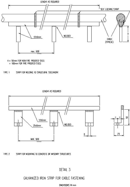
Metallic Strips for Fastening
Metallic strips shall be made by Contractor as shown in below detail 3 and shall be hot dip galvanized. They shall be welded to steel or bolted to concrete or masonry structures.
Conduits
For the application of conduits reference is made to BN-DS-E6.
Installation
Cables shall not be installed if the ambient temperature is below the minimum temperature for installation allowed by the cable manufacturer. (Guide line for min. temp is +4°C). If in exceptional cases installation below this minimum temperature should still be required the instructions concerned from the cable manufacturer shall be strictly followed.
Pulling and laying shall be done by hand without the use of any mechanical auxiliary means except rollers.
Bends made during installation shall never be smaller than the minimum cable bending radius i.e.: single core and paper insulated cables : 15 X cable diameter lead sheathed cables : 15 X cable diameter not lead sheathed cables : 10 X cable diameter
Where jute covered cables run above grade the jute shall be removed and the armour protected with an anti corrosion paint.
For vertical runs cables shall be secured at intervals not exceeding 40 cm. For horizontal runs on trays, ladders and racks, cables shall be fixed only at such intervals to eliminate sag or mechanical tension or every 30 cm if arrangement of cables requires to do so.
Fixing means shall preferably be self locking type straps of polyethylene or grey PVC or mild steel galvanized saddles with 2 fixing holes with a length to suit their duty. Fastening of cables to metal strips (see Cable and Wiring Installation at this page) shall always be with self locking type straps; however at intervals of 150 cm a plastic coated aluminium fixing strip shall be used.
Protection of Cables
Protective pipes or cases shall be provided where cables could be subject to mechanical damage and at floor transitions. (protection extended up to 20 cm above floor level). Pipes shall be hard PVC, cases shall be made of galvanized steel plate with a minimum thickness of 2 mm.
Racks and trays shall be provided with removable protective covers allowing adequate ventilation where cables under normal operation and maintenance conditions may be exposed to: - mechanical damage from falling objects; - damage from leaking fittings of pipelines containing fluids which can attack the outer sheating. However, running of cables underneath such pipelines shall be avoided as much as possible.
Where a cable has to be passed over the flange of a tray or to be dropped out of it the flange shall be turned down and the slot be widened and smoothed. PVC or lead strip (pieces of old cable lead sheath) shall be formed around all related edges to prevent damage to the cable. Provisions shall be installed where cables leave the tray to ensure that bending will be not too severe.
Mounting of cables directly over or within a distance of 30 cm from hot equipment or releases of corrosive fumes is not allowed. Maximum acceptable temperature is 40°C unless cables have been specially designed for high temperature.
Installation of bare copper covered cables or bare copper conductors (e.g. mineral insulated cables, earth wires, etc.) on galvanized material or suchlike is not allowed.
All bolts in cable trays shall be installed pointed outward.
Terminations
All cable entries of electrical equipment in wet locations shall be made at the bottom or sides to prevent the ingress of water.
Cable glands shall be used for termination of low voltage cables up to and including 30 mm outside diameter. For low voltage cables above that diameter and high voltage cables potheads shall be used.
Cable glands shall be of the correct size and type for the cable applied to obtain a firm and watertight entry. Seal of cable gland shall fit the overall diameter of the cable. In no case may mastic or tape be used to allow the use of an oversized cable gland. All cable glands shall be properly sealed with a neoprene shroud or plastic putty to make them waterproof.
For enclosures made of insulating material such as installation cable boxes, lighting fittings, etc. the cable glands shall be of insulating material. For metallic enclosures all cable glands shall be metallic.
Where items of equipment should be delivered without cable glands, however, with threaded inlets only, or even without holes at all, Contractor shall supply glands and do the drilling and tapping required against unit price.
To prevent the cables from being pulled out of glands they shall be secured externally. (approx. 15 cm below the cable gland).
Potheads for low voltage cables shall be left dry and shall be provided with a drain-hole at the bottom.
All cable terminations but high voltage terminations in particular shall be made by skilled electricians. Any recommendations issued by the manufacturer of pothead or high voltage cable shall be strictly adhered to.
All metallic enclosures of electrical equipment shall be earthed via the earth continuity conductor in their supply cables which shall be connected fully at both ends to the earth bus or terminal. The earth conductor shall provided with a green/yellow sleeve.
The armouring of a cable not constructed for equipment earthing shall only be connected to the earth bus in the switchgear. This means also that it must be isolated from the enclosure of the consumer.
The lead sheaths of cables (regardless of their thickness) shall only be connected to the earth bus in the switchgear.
Miscellaneous Requirements
To determine the cut-off length of cables an adequate extra length shall be added to cover the connection itself and a possible slack. Additional slack is required when the equipment is subject to expansion and/or movement.
The ends of underground cables coiled and buried in the trench local to their rising point by others (as meant by BN-DS-E3 point Cable Laying, Cable Terminations) shall be taken out and connected to these boxes by Contractor.
Junction boxes mounted on cable trays, platforms, etc. shall be located such that the front side is easy accessible after erection.
Fireproofing of Electric Cables
Fireproofing of electric power cables is normally not required and even considered undesirable because it reduces the current carrying capacity. However, it might be possible that for safety reasons control of certain critical facilities will be necessary after the outbreak of the fire.
In view of the above the following rules are recommended: - Cables for critical facilities to be installed below ground as much as possible.
- Use of cables with XLPE insulation and flame-retardant outer sheathing (or mineral insulation).
- Parts of relevant cables that run above grade shall be supported by closed cable trays or conduits and be wrapped with respectively aluminium foil, fire insulating tapes and outside metal sheath.
Thickness of wrapping shall be designed such that in case of fire the inside temperature of tray or conduit will remain sufficiently low for a certain time to keep the cables operational.
Fireproofing of cable trays or conduits is only acceptable if control and/or normally non-current carrying power cables (e.g. cables for motorized valves) are concerned.
Other preventive means which may be applied are fire resistant plates mounted under, over or at the side of cable racks but such that normal ventilation is not disturbed.
Details: incl. 1-6