")
Table of Contents
1. Cable Routing
1.1 General Requirements
1.1.1 Cable runs will be preferably routed under pipe racks and along roads, the runs shall be straight, changes of direction and branches must be at right angles.They shall, if possible, be located outside the normal routing of heavy transport. Diagonal area crossing are not allowed.
1.1.2 Cables shall not run both underneath and parallel with pipelines laid in or directly on the ground.Where cables run parallel with underground pipelines or sewers a clearance of minimum 30 cm shall be maintained between pipes and cables.
1.1.3 Directly buried cables will be installed in cable trenches.
1.1.4 Trenches shall be constructed such that adequate and permanent mechanical protection is given to the cables.
1.1.5 Minimum trench depth for excavation is 80 cm for single layer and 100 cm for two layer trenches.
1.2 Trenches in Unpaved Areas
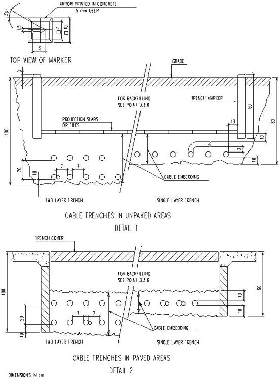
1.2.1 Trenches in unpaved areas have earth side walls and bottom. To provide additional protection and warning to workmen red coloured concrete slabs or tiles must be laid over the top layer of sand or selected backfill. (Tiles preferable 30 x30 x4 cm)For typical cross-section see below figure detail 1.
1.2.2 Bottom width of trenches in unpaved areas will be a full multiple of 30 cm.
1.2.3 Asphalt or brick covered areas are to be considered unpaved.
1.3 Trenches in Paved Areas
Trenches in concrete paved areas shall have an earth bottom and concrete walls or similar means, to prevent the supporting ground of the paving from caving-in. No protection slabs or tiles are required. A red coloured weak concrete covering layer shall be provided on these trenches and constructed such that :- fluids present on the surface cannot enter the trench.
- the cover is resting on the backfill, so not supported from the side walls, to avoid airpockets between cover and backfill.
1.4 Crossings
1.4.1 Where cables have to pass under rail- and pipe- tracks they shall be installed in concrete ducting. For various type of ducting see point 3.2 hereafter.
1.4.2 No special provisions should be made for cables crossing roads or dikes, except the installation of spare conduits up to 10-20% of trench capacity, for future cables.
(For installation of conduits see standard BN-DS-E6) This is to avoid disturbing the finished roads or dikes afterwards.
1.4.3 In cases where cables have to cross/pass hot underground pipes or equipment, they must be protected either by observing adequate spacing or by insulating the hot pipes or equipment in order to limit the maximum temperature at the location of the cables to 30oC.
1.4.4 At crossings of instrument and electrical cables the instrument cables shall always run on top.
A minimum distance of 30 cm shall be observed between the lowest cable in the instrument trench and the highest cable in the electrical trench.
1.4.5 In cases where cables have to cross underground pipelines or sewers a vertical clearance of min. 30 cm shall be observed.
2. Cabling Design
2.1 General
2.1.1 All continuous load carrying cables shall be horizontally spaced with a min. interval of 7 cm.
2.1.2 Space is not required between normally unloaded cables (such as control and lighting sub-circuit cables) or between normally unloaded and loaded cables. Motor control cables shall be laid along their associated motor feeder cables.
Wherever practical, motor feeder cables in the same trench which serve normal and spare services shall be laid alternately
2.1.3 Where large groups of cables must pass through congested areas and space restrictions do not permit cables to be laid in a single layer, cables may be installed in a maximum 2 layers provided that :
-
vertical separation between the layers is minimum 20 cm.
-
space for future cables, when required, is made available in the top of layer.
-
the high voltage cables are installed in the bottom layer.
2.1.4 When a cable is to cross other cables to leave the layer a filling of minimum 3 cm. clean sand between that cable and other cables is required.
2.1.5 In the order to avoid overheating of the cables, the above mentioned spacings have to be maintained at all times. Parallel feeders should be separated from each-other as much as possible, e.g. on opposite sides of the trench.
2.1.6 Top of cables will be installed at a depth of minimum 55 cm below grade.
2.1.7 For cable arrangement in trenches and ducts see below figures details 1, 2 and 4.
2.1.8 Cables are routed in conduits from the trench to the individual equipment e.g. pumps, outlets junction boxes etc.
2.1.9 For application of conduits see standard BN-DS-E6.
2.2 Cables for Special Purposes
2.2.1 Cables for special purposes i.e. communication, electronics, etc. shall run separate from power-earthing and lighting cables to minimize interferences.
2.2.2 They shall not be laid in the same trench with electrical cables, so separate trenching is required.
2.2.3 Unless overruled by a special job specification, the following minimum clearances between the special and electrical cables should be maintained :
crossings =30 cm
parallel runs =60 cm.
2.2.4 Main cables for uninterrupted power - and emergency supply systems shall be handled in the same way as special cables.
2.2.5 installation practice of these cables should follow the prescriptions for normal cables.
3. Installation Requirements
3.1 Excavation
3.1.1 Excavation shall be carried out to the Engineer’s satisfaction with approved earth moving equipment to the levels and dimensions shown on the drawings and with side slopes appropriate to the type of soil.
3.1.2 All excavated soil that has been approved by the Engineer for backfilling shall be placed in principle not more than 5 m away from the trench at locations agreed with the Engineer.
If it is not possible to place this soil near the trench it is to be transported to stockpiles as directed by the Engineer.
3.1.3 If in the course of excavation Contractor encounters any underground pipe-lines, sewers, cables or any other undocumented obstruction, he shall immediately ask the Engineer for instructions.
Note : The position of existing underground pipe lines, sewers, cables, etc. where shown on the drawings are not guaranteed either accuracy or completeness and Contractor shall verify their positions before commencing any work.
3.1.4 Excess cuts shall be filled to the correct level with compacted material in accordance with this standard at Contractor’s expense.
3.1.5 It shall be Contractor’s responsibility to keep the excavations free of storm and seepage water until the work has been completed and to install and maintain all shoring, sheet piling, and the like temporary work, necessary to maintain the excavated trenches in a suitable condition to carry out the work, and to prevent sliding of earth or settlement of adjacent ground, structures or other works.
3.1.6 At no time the installation and removal of Contractor’s temporary works and dewatering facilities shall adversely affect other areas of construction.
The responsibility for means and methods of design and installation of the temporary works rests with Contractor, but all methods shall be approved by the Engineer prior to carrying out.
3.1.7 Safety barriers along the sides of open trenches and accesses across trenches shall be provided by Contractor. Locations shall be mutually agreed with the Engineer before starting excavation.
All barriers shall be well maintained throughout the period that trenches are open. Where they are temporarily removed to facilitate the installation of cables, they shall be reinstalled before leaving the job site.
3.2 Ducting
3.2.1 General
In general the length of any ducting should not exceed 20 m. Where soil conditions are poor a reinforced concrete slab shall be made to support and hold the ducting and to prevent damage to cables due to independent movement of duct sections. When a duct can lead fluids from one area to another, the whole duct has to be sealed off at the possible fluid entrance. During construction the whole duct and after installation the spare holes must be plugged-off at both ends with wooden plugs or suchlike.
3.2.2 Ductbanks
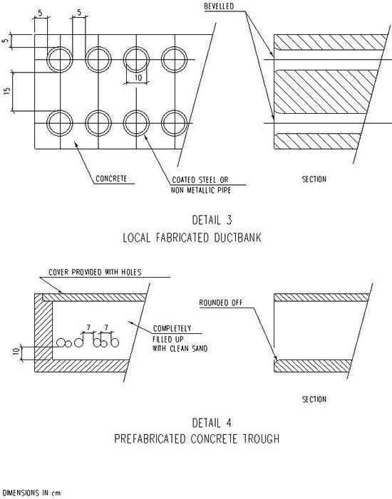
Ductbanks will be made up from coated steel- or non metallic pipes (including 20% spare) encased in concrete. The ends of the pipes shall bevelled to avoid damaging of the cables. For typical cross-section see below figures detail 3.
3.2.3 Concrete Troughs
In cases where normal prefab. concrete troughs are required, they have to be filled with approved filling material after cable laying to avoid over-heating of the cables. For typical cross-section see below figures detail 4.
3.2.4 Cable Form Stones
Cable form stones shall be in accordance with DIN 457. They shall be 1 m long with holes of approx. 100 mm diametre, but without bituminous coating on the inside. They shall have holes and dowel pins for alignment of adjacent units. When stones have been fitted together all joints shall be plastered.
3.3 Cable Laying
3.3.1 General
The following considerations shall apply for cable pulling operations :
-
In principle pulling of cables shall be done by hand without mechanical auxiliary equipment.
Note : If Contractor should propose to pull a certain part of the cables with power-driven mechanical pulling equipment he shall submit :
a. A reference list of previous mechanical cable pulling jobs.
b. A full description of the pulling equipment proposed which shall at least be specifically designed for this purpose with all necessary features to prevent damage to the cables such as torque limiting devices. It shall further be fitted with a recorder to record all pulling activities. Recording rolls must be handed over to the Engineer marked up with type and cable number concerned.
-
In all cases sufficient manpower shall be available near the cable reel to drive and stop it in time
-
Maximum use must be made of rollers particularly by changing of direction and long runs.
-
Manufacturer’s maximum recommended cable pulling tensions shall not be exceeded.
-
For steel wire armoured cables tension shall be applied to the wire armour and for steel tape armoured cables tension shall be applied only to the bunched conductors.
-
Contractor shall keep the job site clean and tidy at all times. Cable drums, sand, tiles, rollers, etc. , shall not be stored to block access ways and roads.
-
Drum reeling points shall be selected to give minimum interference with traffic.
3.3.2 Cutting Lists
Prior to starting the pulling of cable Contractor shall prepare a complete cutting list for each cable reel in order to use the continuous cable lengths supplied most economically.
Note: The lengths indicated on the cable lists are to be considered informative only. The actual lengths have to be verified in the field and on the reels. If certain lengths have been specifically ordered to avoid splices, these will be marked up in the cable lists. These designated lengths may only be used for the service indicated.
3.3.3 Underground Laying
Before commencing the installation of the cables Contractor shall make the trench bottom flat, clean and free of any hard or sharp objects, and assure access through road - and pipetrack crossings.
Cables will not be installed if the ambient temperature is below the minimum installation temperature as given by the cable manufacturer. If installation below the minimum temperature is required after all, the instructions concerned from the cable manufacturer shall be followed. (Guide line for the minimum temperature is +4oC.) Cables shall be routed as indicated on the relevant cable layouts. Any deviation thereof shall be shown on the as-built drawings.
Cables shall be laid as indicated on detail 1 through 6, see below figures. The minimum bending radius for cables shall be 15x but for lead sheathed single core - and minimum sheathed paper insulated cables 25x the cable diameter. Fixed bends at terminal boxes may have a radius of 70% of the above mentioned figures, provided that they are made by skilled labour.
The cable arrangement will be such that cross-overs are restricted to the absolute minimum.
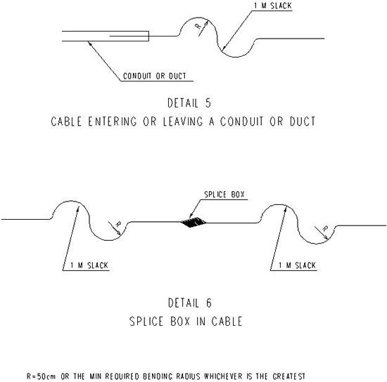
Cables shall be laid slack to prevent breakage due to settlement of the ground. In addition a slack of 1 m is required when a cable enters or leaves an underground conduit or ducting. (see below figures detail 5)
All cables shall be identified with cable markers. For cable identification see standard BN-DS-E4.
Care must be taken when unreeling cable from drums and passing ends through ducts, etc., that twists and kinks are not made in the cable.
The conduits required to route cables from the main trench to the individual equipment shall be supplied and installed by Contractor when not installed by third party. (e.g. Civil Contractor)
3.3.4 Cable Splices
Normally, cables shall be installed in single continuous lengths. Splices shall only permitted in exceptional cases. The necessity for splices and their proposed location shall be subject to the Engineer’s approval.
When direct burial cable splices are made, proper splice materials shall be used and a slack of 1 m shall be applied at both sides of the splice box (see below figures detail 6). The location of splices shall be shown on the as-built drawings.
3.3.5 Cable Terminations
Immediately after cutting, all cable ends both of the installed cables and of the cable part remaining on the reel shall be protected as follows:
-
XLPE and PVC insulated cables to be liberally wrapped with “denso” tape.
-
Paper insulated cables to be capped by a plumbed lead cap over the conductors.
-
Telecommunication and thermo-couple extension cables to be closed by means of cast resin.
-
Multicore tubing cable to provided with suitable caps securely taped to the cable.
The ends of the cables which should run above ground have to be coiled by Contractor in the trench local to the equipment and backfilled and indicated as such above the backfill until the time they will be connected or run overhead to equipment.
Note : Information regarding the necessary length of the cable to be coiled will either be indicated on the drawings or has to be determined by Contractor for those drawings where the overhead part of cable run has been completely shown.
Contractor is responsible for supporting and protecting all loose ends of cables remaining above grade to prevent damage until final termination. Prior to entering substations or control room (basements) cable ends shall be cleaned from sand and dirt.
3.3.6 Backfilling of Trenches
No trenches shall be backfilled unless approved by the Engineer.
If excavated soil has been disapproved by Engineer for backfilling purposes clean sand or special backfill will be placed at Contractor’s disposal.
The backfill shall surround the cables to a thickness of 10 cm. It shall be well compacted by tamping and watering to a minimum density of 95% Proctor in order to improve the thermal conductivity.
A protective covering of red concrete tiles shall than be applied (for trenches in unpaved areas only) and the remainder of the trench be backfilled and tamped.
The backfill shall be thoroughly screened to eliminate hard and sharp objects.
3.4 Cable Trench Identification
3.4.1 Trench routing and ducts in unpaved areas shall be identified by trench markers.
3.4.2 Trench markers are to be 10 cm square red concrete posts, 60 cm long located as follows:
-
Minimum every 10 m inside process battery limits.
-
Minimum every 25 m outside process battery limits. (off-site)
-
At all points where trench changes direction and branches-off.
-
At both edges for trenches 90 cm wide and above.
-
At one edge for trenches under 90 cm wide.
These markers shall protrude 2 cm above grade.
3.4.3 Trench markers will be made and placed in accordance with detail1, see below figures.
3.4.4 Trench in paved areas are identified by their red concrete cover
3.5 Damages
Cables damaged prior to installation shall not be repaired and installed unless approved by the Engineer. Cables damaged due to rough or unskilled handling or other ways of wrong handling by Contractor during or after installation shall be immediately repaired at Contractor’s expense, in order to prevent further deterioration.
The method of repair shall be in accordance with cable manufacturer’s instructions.
All coating and wrapping of underground piping damaged by Contractor during trench work and cable laying shall be repaired at his expense.
All damages shall be reported to the Engineer immediately.
3.6 Verification and Testing
3.6.1 General
All test equipment required shall be furnished by Contractor at no extra cost and shall be subject to approval by the Engineer for accuracy, calibration and suitability for intended function. During installation of cables Contractor shall verify:
-
Actual length of cable above ground and the exact location of the cables.
-
Provisions to protect the cables.
-
Sealing of cables and holes.
-
Cross sections/numbers of cores, type and voltage of the cables and correct tagging.
-
Laying, spacing and bending radii of cables especially those parts coiled-up in trenches for later above ground installation.
-
Protection of ends of cables.
-
Density of soil before laying of cables.
3.6.2 Cable Testing
Test of insulation resistance and continuity of all conductors and, where applicable, continuity of metallic shielding shall be made after installation and before backfilling of trench.
A 5000 V Megger shall be used for all cables of 6.6 kV rating.
A 1000 V Megger shall be used for all cables of 750 V rating.
A 250 V Megger shall be used for all lower rating cables.
3.6.3 Records
Records of the results for each test shall be submitted to the Engineer on a weekly basis.
Figures: