Gate Valves - Carbon Steel
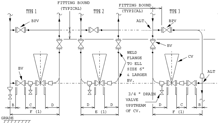
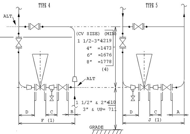
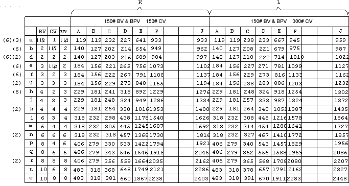
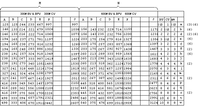
This design standard provides overall dimensions of flanged control valve manifolds. The dimensions are for study purposes only. The final dimensions should be checked against the data from the piping- and (control) valve manufacturer.
Legend of abbreviatons:
CV - Control Valve
BV - Block Valve
BPV - Bypass Valve
ALT - Alternative Flow
Notes:
- Inludes gaskets 2 thicknesses for 150#-300# and 3 thicknesses for 600#
- Use filler of equal length where reducer is not used
- Use swage reducer
- When air fins are specified, check with instrument engineering for additional height requirements
- Dimensions based on Mason-Neilan 10000 control valves (bulletin No 343E dated 5/10/74)
- Globe valve BPV
Example:
Type #Lm indicates type 3 arrangement of control valve manifold with 4" 300# control valve (CV), 6" 150# gate valves as block valves (BV), 4" 150# gate valve as by-pass valve (BPV)
Notes on metric dimensions:
These dimensions are a conversion from the imperial (inch) dimensions standard with each dimension rounded to the nearest whole millimeter. The overall dimensions may not always correspond to the exact sum of the lengths of component parts given in millimeters.
 |
Size
|
1
|
1 1/2
|
2
|
3
|
4
|
6
|
8
|
10
|
|
|
150
|
U
|
-
|
165
|
203
|
241
|
-
|
-
|
-
|
-
|
|
|
V
|
-
|
-
|
-
|
203
|
229
|
267
|
292
|
-
|
||
|
W
|
330
|
330
|
330
|
381
|
381
|
445
|
527
|
-
|
||
|
X
|
559
|
572
|
600
|
746
|
749
|
972
|
1057
|
-
|
||
|
Y
|
184
|
222
|
254
|
298
|
352
|
451
|
543
|
-
|
||
|
Z
|
-
|
165
|
178
|
203
|
229
|
267
|
292
|
330
|
||
|
300
|
U
|
-
|
229
|
267
|
318
|
-
|
-
|
-
|
-
|
|
|
V
|
-
|
-
|
-
|
283
|
305
|
403
|
419
|
-
|
||
|
W
|
330
|
330
|
330
|
381
|
381
|
445
|
527
|
-
|
||
|
X
|
559
|
572
|
600
|
746
|
749
|
972
|
1057
|
-
|
||
|
Y
|
197
|
235
|
267
|
318
|
368
|
473
|
568
|
-
|
||
|
Z
|
-
|
191
|
216
|
283
|
305
|
403
|
419
|
457
|
||
|
600
|
U
|
-
|
241
|
292
|
356
|
-
|
-
|
-
|
-
|
|
|
V
|
-
|
-
|
-
|
356
|
432
|
559
|
660
|
-
|
||
|
W
|
330
|
330
|
330
|
381
|
381
|
445
|
527
|
-
|
||
|
X
|
559
|
572
|
600
|
746
|
749
|
972
|
1057
|
-
|
||
|
Y
|
210
|
251
|
286
|
337
|
394
|
508
|
610
|
-
|
||
|
Z
|
-
|
241
|
292
|
356
|
432
|
559
|
660
|
787
|
||


