")
This design standard gives the basic dimensions for plot arrangement of equipment and a typical section thru pipe way or pipe rack.
Arrangements
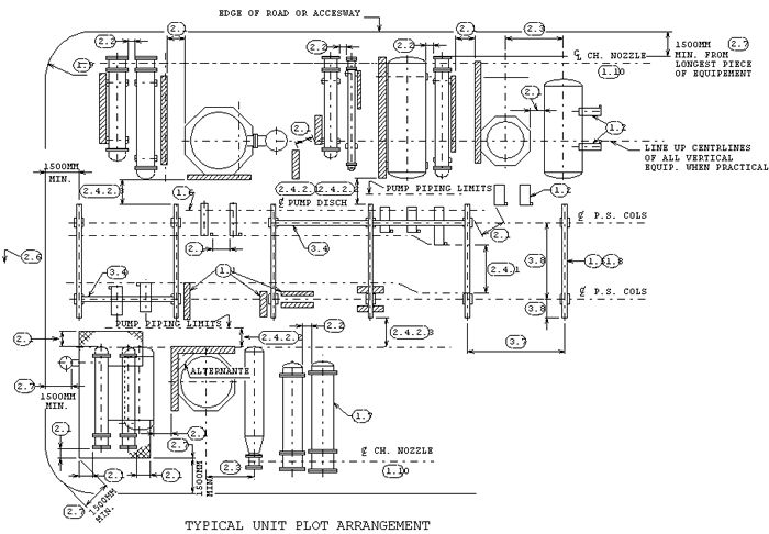
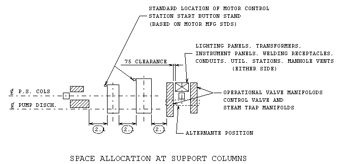
| 1.1 | Preferred locations for piping control valve manifolds, operational valve manifolds, traps etc. |
| 1.2 | Pumps with low suction lines shall be located as shown, providing access is available for maintenance |
| 1.3 | Pump suction lines shall be as short and direct as piping flexibility allows. |
| 1.4 | Pump suction adn discharge piping shall preferably be located within pipeway overhang to provide overhead support from members connecting to pipe raci |
| 1.5 | When process conditions permit and it is economically preferable, air coolers shall be installed above overhead pipeways |
| 1.6 | When proctical and economical, pump discharge nozzle centerlines to be aligned |
| 1.7 | For typical arrangement of exchangers and handling facilities, refer to BN-DS-C48 |
| 1.8 | For typical arrangement of air coolers and related piping, refer to BN-DS-C49 |
| 1.9 | Road radius is equal to width of road, unless job specified otherwise |
| 1.10 | Exchanger channel nozzle centerlines to be aligned |
Equipment and Pipeway Clearances
| 2.1 | 900 clear walking space for passageways (may be measured on diagonal), 700 minimal clearance allowed |
| 2.2 | Clearance between flanges of exchangers or around other bolted equipment connections, which must be serviced or maintained, shall be 450 clear. |
| 2.3 | Minimum dimension as required to clear foundation footings when individual foundations are used. |
| 2.3.1 | Dimension to be calculated, when combined footings are utilized |
| 2.4 | The cross section of the pipeway relative to equipment shall be controlled by the following clearances: |
| 2.4.1 | Unless other means can be provided for access to pumps, a 3600 minimum clear accessway shall be provided which will furnish sufficient space for pickup truck maneuvering, but which may not necessarily be in a straight line |
| 2.4.2 | Clear aisleway for exchanger shell cover removal shall be: |
| 2.4.2.1 | 1800 clear to provide shell cover end totally accessible from aisleway when using fork lift or portable "A" frame |
| 2.4.2.2 | 1200 clear when a mobile crane is positioned at channel end to remove shell cover |
| 2.4.2.3 | 1200 clear if shell cover can be removed by forkift or pipeway overhang where insufficient vertical clear height is not available for services entering or leaving pipeway |
| 2.5 | Pipeway bottom of pipe elevations above grade or hight point of paving shall be 2100 over passageways and 3600 over accessways |
| 2.6 | Overhead clearances: |
| - Roadways - 4800 (crown to bottom of lowest member) | |
| - Railways - 6700 (top of prails to bottom of lowest member) | |
| 2.7 | Drainage ditch requirement may increase this dimension |
Pipeway
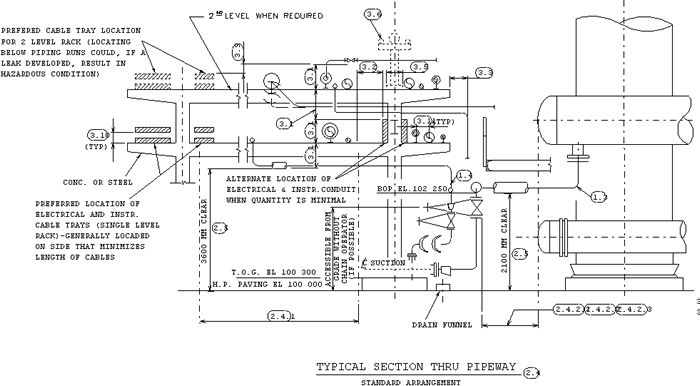
| 3.1 | Pipeway elevations are established by the largest branch to header combination on the piperack. Use a 90 % and 45% elbow combination or a 45% branch on large lines. Use a minimum of 650 between elevations on the piperack |
| 3.2 | Leave a clear space for risers to the upper rack |
| 3.3 | Keep the vertical lines on the same centerline and keep 50 clear from edge of the overhang to edge of pipe or insulation |
| 3.4 | Investigate the use of hangers or brackets instead of longitudinal steel to support lines leaving the piperack |
| 3.5 | Leave space over column centerline for additional pipe supports |
| 3.6 | Flare lines or sloping lines can be run on tee supports above the rack |
| 3.7 | Standardize on spacing of pipeway bent supports when practical, refer BN-DS-C25 and BN-DS-C26 for pipe spans to determine spacing of supports |
| 3.8 | Pipeway bent support widths are determined by the number of lines, levels and access requirements |
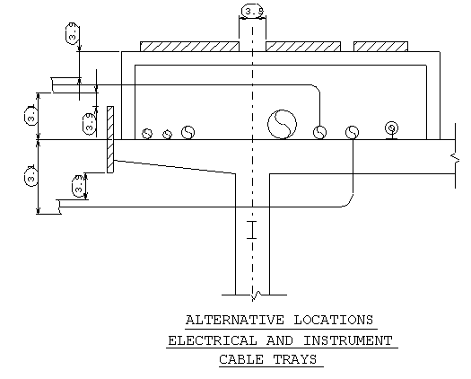
| 3.9 | Lines crossing a cable tray shall be 150 clear of tray |
| 3.10 | Distance between cable tray shall be 450 |
| 3.11 | See BN-DS-C42 for pipe spacing standard |