Table of Contents
1. General
1.1. Function
The primary function of a fired heater is to supply all heat required by the process in one form or another. A fired heater utilizes gaseous or liquid fuels often produced as a by-product. The normal process function is raising the process stream to its required temperature for distillation, catalytic reaction, etc. Sizes of heater vary considerably, dependent upon the type of duty and throughput.
1.2 Types
There are two general basic designs or types of fired heaters:
- Box type
- Vertical type.
Either of which may be forced or natural draft.BoxType Heaters (See below figures 2 and 3.)
A box type heater is considered to be any heater in which the tubes are horizontal. In this type of heater it is possible to have locations or zones of different heat densities. The zone of highest heat density is the "radiant section". The tubes in this section are called "radiant tubes".
The heat pickup in the radiant tubes is mainly by direct radiation from the heating flame. In some heater designs shield tubes are used between radiant and convection section. The zone of lower heat density is the "convection section". The tubes in this section are called "convection tubes". This heat pickup in the convection section is obtained from the combustion gases primarily by convection.
Box type heaters may be up-fired or down-fired with gas or oil fired burners located in the end or sidewalls, floor, roof or any combination thereof.
Up-fired Heaters
In the horizontal up-fired heater, products of combination in the radiation chamber pass upward through banks of roof tubes and a fire brick diffuser into a plenum or collecting chamber. From the plenum chamber flue gases are passed through an overhead convection section and then to an overhead stack. Such heaters may be fired vertically upward by panels, mounted in the heater floor or hearth, the heater floor being elevated to provide headroom beneath. Alternatively, these heaters may also be fired horizontally by burners mounted in the heater-end walls, in which case the heater floor is only elevated above grade to provide air cooling convection to the heater foundations. This type of heater may contain single or multiple radiation chambers discharging flue gases to a common convection section and stack.
Down-fired Heaters
In the down-fired heater, combustion gases generated in the radiant chamber pass downwards through a refractory checker hearth into a collecting chamber beneath. From there the flue gases flow upward through the convection section and then out to the stack. The down-fired heaters are basically intended to fire on heavy residual fuels, where the flue gases are corrosive and may clog flue gas passages of conventional heaters.
Convection sections are thus protected by removal of combustion solids and are usually provided with inspection ports, soot blowing devices and tube facilities to keep the coils clean. Burners in down-fired heaters are always mounted in the heater-end walls.
Vertical Heaters (See below figures 4,5 and 6) Vertical heaters are either cylindrical or rectangular. They may have radiant section only or convection and radiant sections. The radiant section tubes will usually be vertical, but some cylindrical heaters have helical coils. The convection section can be either vertical of horizontal.
Types of Heater Firing
Heaters can be fired from any position, i.e. bottom, top, side or end.
By far the most common is bottom fired, mainly because it is more economical. The burner of a bottom fired heater will be located 2.1-2.7 M above grade at a height which is suitable for an operator to work underneath. Operating from under the heater is more dangerous than other types of firing, which is the principle reason certain operating companies will not install a bottom fired heater.
Heaters are commonly light with an electric ignitor. some refineries use a propane torch while some still light the burners with a rag soaked in spirits or kerosene.
Forced or Natural Draft
Consideration must be given at the layout stage to accommodate the additional equipment associated with a forced draft heater. This will usually comprise an air inlet duct with silencer, forced draft fan and an air preheater. The inlet duct may require a support structure.
2. Location
Heaters are always located at a safe distance 15 meters away from other hydrocarbon bearing equipment and preferably upwind; however, on some process it is permitted for reactors to be within this distance to prevent light volatile vapors from begin blown towards an open flame.
Space must be allowed for tube replacement for both horizontal and vertical heaters and this, together with ample access for mobile equipment, should be considered on piping layouts and drawings. Ample access is always needed for firefighting equipment with areas under or around heaters usually paved and curbed.
No low points in the paving or grading are permitted as these provide excellent sports for trapping hydrocarbon liquids which could be ignited by the open flames of the burners.
3. Safety
3.1 Snuffing Steam Station
See below figure 7.
Snuffing steam connections are supplied by the heater manufacturers, generally in the combustion chamber and header boxes.
The control point or snuffing steam manifold is generally located at least 15 meters away from the heater, is supplied by a live steam header and is ready for instantaneous use. Smothering lines should be free from low pockets and should be so arranged as to have all drains grouped near the manifold.
Collected condensate (apart from freezing and blocking lines) can, when blown into a hot furnace, result in serious damage. (Low points should be drilled 10 mm diameter or provided with spring opening auto-drain valves).
3.2 Monitor Nozzles
Some customers request that turret or monitor nozzles be located around the heater so that water for fighting a fire is instantly available. Controls for such nozzles should be located at least 15 meters away from the heater.3.3 Utility Stations
Steam, air and service water connections should be provided near tube-ends of heaters. 3.4. Process Control StationsProcess feed and discharging block valves and flow control valves shall be located at a distance from the heater, if indicated as necessary by the engineering flow diagram or instructed by the Piping Specialist Engineer or Project Department.3.5 Explosion Doors
Piping shall not obstruct explosion doors or tube-access doors.
4. Inlet and Outlet Piping
See below figures 8 and 9.
Flow distribution through a multipass heater is affected by the inlet and outlet manifolding. The piping arrangement at the inlet of the furnace is the more critical and requires careful attention.
4.1 Inlet Piping
Inlet piping should preferably be symmetrical and of the same length from the point where flow splits to the heater inlets. This refers to the number of bends, elbows and valves, as well as the number of straight runs of pipe and their location. piping should avoid dead-end tee branches and sharp turns. Unequal flow through any part of the heater would result in deposits of coke and overheating of tube walls.
4.2 Outlet Piping
On outlet piping, symmetry is not as critical as on the inlet; however, nonsymmetrical piping may contribute to possible coking and overheating of tubes. A nonreturn and a shutoff valve is usual at the outlet of the furnace to eliminate any reverse in the case of tube failure.4.3 Flexibility
Because of the high temperature involved and length of pipe runs required to isolate the heaters, piping flexibility must be examined carefully. Some heater manufacturers will permit a limited amount of tube movement to take all or part of the piping expansion. This possibility should be investigated in conjunction with the Stress Department, by the Piping Design Office during the study stage. It is generally necessary to anchor the piping adjacent to the heater to remove stresses from the nozzles.5. Burner Piping
See below figures 8 and 9.Supply of fuel to individual burners is adjusted by individual valves. These should be so located that the burners can be operated while observing the flame through peepholes or burner openings.
All burner leads for gas and steam (atomizing) must be taken from the top of the headers, and fuel gas piping should be so arranged that there are no pockets in which condensate could collect. The fuel oil header must have full circulation; under no condition shall it be a dead-end line. Noncirculating branches to burners should be as short as possible or insulated together with atomizing steam.
A ring header around the furnace mounted a short distance above the peepholes, having vertical leads adjacent to the vertical doors to the burners, provides the greatest degree of visibility from the operator’s point of view.
Atomizing steam to be used in conjunction with fuel oil shall be taken the main steam supply header at or near the heater. Steam traps shall be provided to drain all low points in the atomizing steam system. Separate leads to each burner shall be taken from the top of the atomizing steam subheader. Shutoff valves shall be so located that they can be operated while observing the flames from the observations ports.
6. Decoking and Sootblowing
6.1 Decoking
(See below figure 12)The internal cleaning of tubes and fittings may be accomplished by several methods. One is to circulate gas oil through the coil after the heater has been shutdown but before the coils are steamed and waterwashed and prior to the opening and start of inspection work.
This method is effective if deposits in the coil are such that they will be softened or dissolved by gas oil. When tubes are coked or contain hard deposit, other methods may be used, such as steam air decoking and mechanical cleaning for coke deposits and chemical cleaning for salt deposits. Chemical cleaning and steam air decoking are preferable as they tend to clean the tube to bare metal. The chemical cleaning process requires circulation of an inhibited acid through the coil until all deposits have been softened and removed. This is usually followed by water washing to flush all deposits from the coil. Steam air decoking process consists of the use steam, the coil. Steam air decoking process consists of the use of steam, air and heat to remove the coke. The mechanics of decoking are:
a. Shrinking and cracking the coke loose by heating tubes from outside while steam blows coke from the coil.
b. Chemical reaction of hot coke with steam.
c. Chemical reaction of coke and oxygen in air.
Steam and air services are permanently connected to the heater. The heater outlet line incorporates a swing elbow which, during the decoking operation, is disconnected from the outlet line and connected to the decoking header. Care must be taken to allow sufficient access and platforming when the swing elbows are changed over. Coke is carried by this header to the drum or sump.
In some instances it may requested by the Process Department or Client that the decoking manifold is connected to allow for reverse flow during the decoking.
6.2 Soot Blowing
In some heaters the convection section contains tubes with extended surface in the form of either fins or studs. Extended surface tubes are used to increase the convection heat transfer area at low capital cost. Because of the tendency of extended surface tubes to foul when burning heavy oils, sootblowers are usually installed.Sootblowers employ high pressure steam to clean the tube outer surfaces of soot and other foreign material. Sootblowers may be either automatic electric motor operated by a pushbutton at grade, or manual requiring operation from a platform located at the convection bank level. Care must be taken that sufficient clearance is allowed for the withdrawal of sootblowers.
Generally heaters are supplied with sootblowing facilities in the convection section although tubes may not be of the extended surface type.
7. Instruments
7.1 Stack
a. Damper: Mechanical or pneumatically operated to control the draft through the stack.
b. Draft gauge (P and I)
c. Flue temperature (TI)
d. Orsat (O2 CO CO2 analyzer).
Instruments b., c. and d. are used to access the correct combustion conditions. Steam is supplied for the Orsat connection in the stack. Water is supplied to the O2 analyzer. Platforming for the access to the stack instruments is supplied with the heater.
7.2 Heater Body
a. Skin thermocouples or tube wall TI’s: to indicate overheating of tubes.
b. PI’s: to measure the draft pressure through the combustion section of the heater.
Figures 1-11 incl.
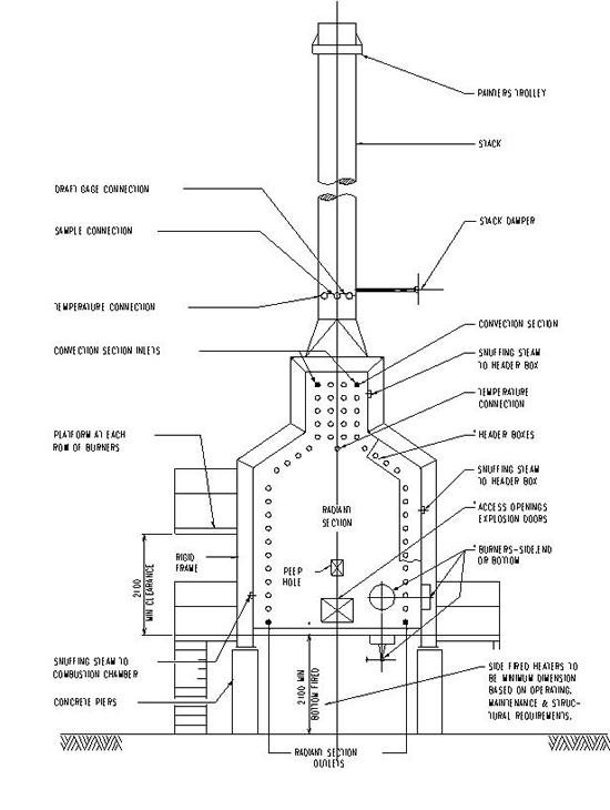
Figure1. BOX TYPE HEATER PLAN
Figure 2. PROCESS PIPING BOX HEATHER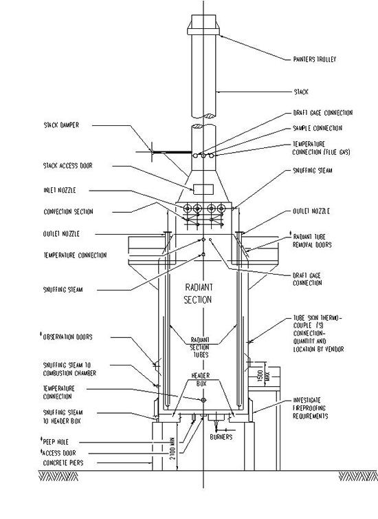
Figure 3. VERTICAL HEATER WITH RADIANT CONVECTION SECTION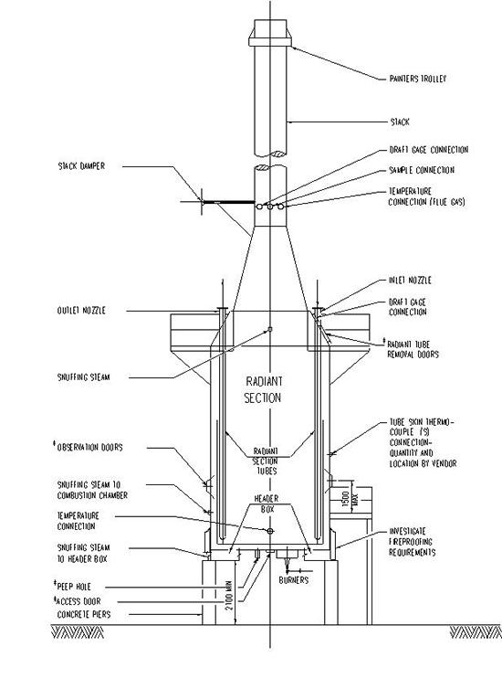
Figure 4. VERTICAL HEATER WITH RADIANT SECTION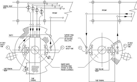
Figure 5. Plan Process Piping at Vertical Heater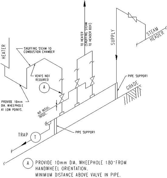
Figure 6. SNUFFING STEAM STATION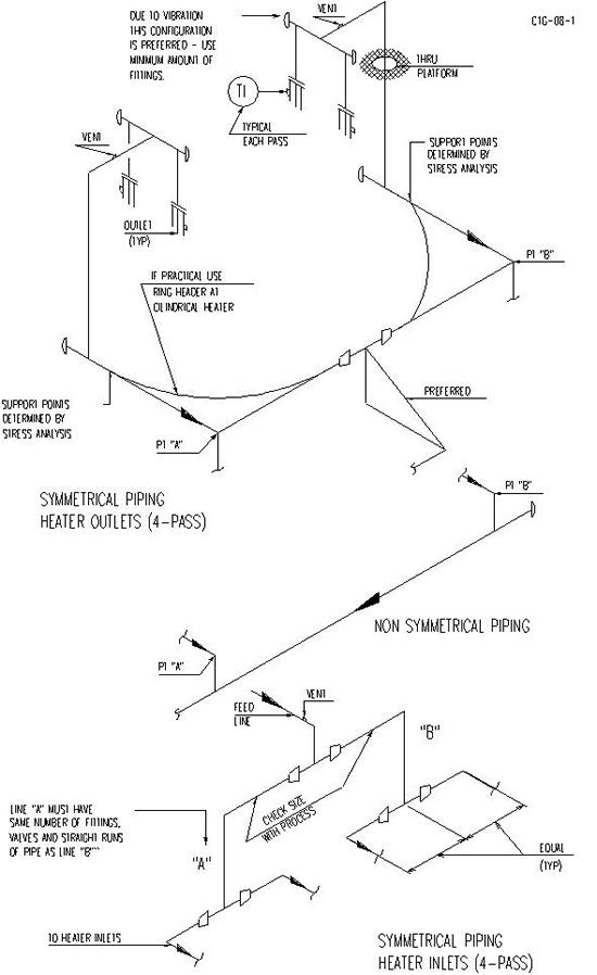
Figure 7.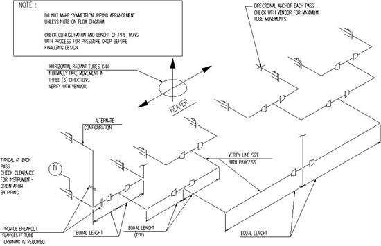
Figure 8.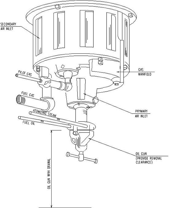
Figure 9. Natural Draft Burner For Fuel Oil/ Fuel Gas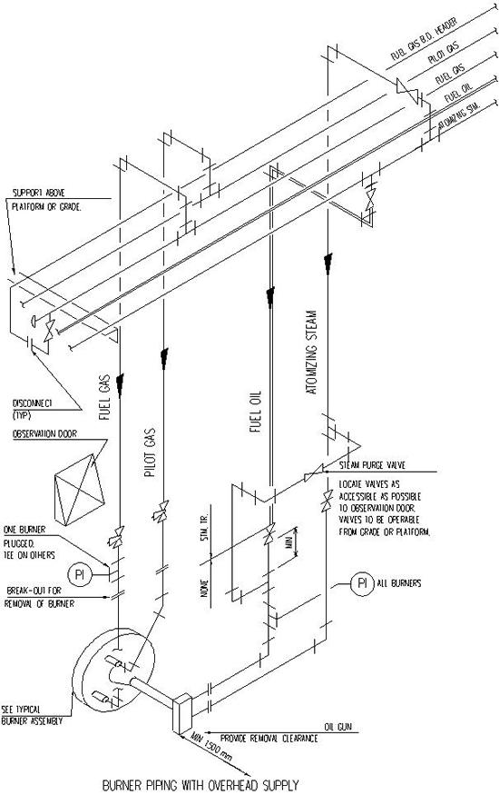
Figure 10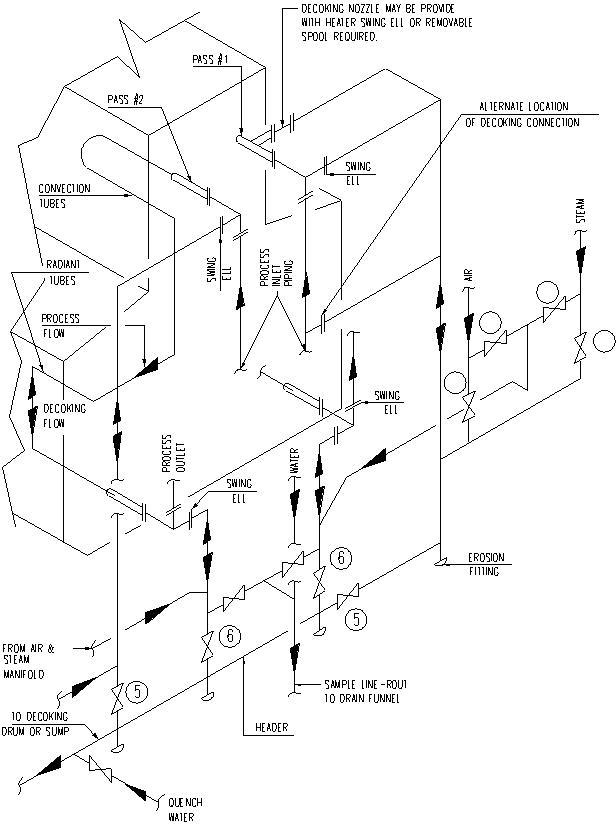
Figure 11
DECOKING PROCEDUREAFTER TUBES BECOME HEADED, STEAM IS INJECTED AT CONVECTION INLETS, VALVES “1”, “2”, “4” & “5” ARE CLOSED “3” IS OPEN.
TO START BURNING, STEAM FLOW IS REDUCED. AIR IS INTRODUCED BY OPENING VALVE “4”. FOR REVERSE FLOW, VALVES “2”, “3”, “4” & “6” ARE CLOSED, “1”& “5” ARE OPEN. VALVE “2” IS OPENED ONLY IF REVERSE BURNING IS REQUIRED. WHILE PASS “1” IS BEING DECOKED, STEAM IS INJECTED INTO PASS “2” TO KEEP TUBES COOL.

