Table of Contents
1. Scope
This specification covers the standard packing and marking instructions for equipment and materials to be shipped for the construction of plants. All shipments, whether scheduled for immediate use or for delivery to storage, shall comply with this procedure, unless other wise specifically required by each project. Any change from this procedure and the special requirements for the specific project are shown in the shipping instructions issued for each project.
This procedure is applicable to any vendor who delivers equipment, materials, or other supplies. Information and specifications stated in the inquiry, requisition, purchase order, or shipping instructions shall take precedence over these requirements.
These requirements are specified so that the equipment and materials will endure the rigors of:
-
handling, stacking, and transportation up to plant jobsites
-
outdoor storage for a period of six (6) months
-
weather exposure from the time the equipment is uncrated and set on its foundation until plant startup, which may be as long as one year later.
2. Preservation and Packing
2.1 Preparation of Material
2.1.1 General
Prior to packing, all equipment and materials shall be checked internally and externally to ensure that they are free from all weld spatter, scale, rust, cuttings, filings, etc., as well as all foreign materials.
Critical wearing surfaces shall be cleaned by dipping or brushing with a suitable solvent, such as petroleum, naphtha or alkaline cleaning compound.
After hydrotesting, operation or performance test, all fluids (e.g. lubricating oil, fuels or water) shall be completely drained from all tanks, vessels, jacketing, piping, etc., and wiped or blown dry. Lint-free rags shall be used for wiping.
2.1.2 Painting and Rust Prevention
Painting and rust preventive coatings shall be checked by the Company inspector when they are required by the specifications for individual pieces of equipment and materials.
2.1.3 Protection of Openings
Flanged openings shall be protected with bolted-on wooden veneer plywood (minimum 5.5 mm thick) or metal covers using at least three bolts. Wiring on the cover is not acceptable. For metal covers, the appropriate gasket shall be used between the flange and its cover. For veneer plywood covers, the joint shall be wrapped with water proof adhesive tape, such as gum tape, after the opening has been covered.
Porous bags filled with desiccant shall be hung on the inside of the wooden or metal covers on all major connections of rotating equipment, unless sizes are restricted physically.
Unconnected pipe threads to be used in normal operation shall be closed with threaded metal plugs or caps. They shall be identified with metal tags explaining the purpose and/or providing connection number used on the project and vendor drawings.
All closures that are part of original equipment shall fit tightly. Plastic closures and thread protectors are prohibited.
Nesting of tubes, unless otherwise agreed, is not permitted.
2.1.4 Flexible Connections
All flexible connections subject to possible damage during shipment shall be disconnected and loose ends shall be adequately supported or protected to prevent damage.
2.1.5 Shaft Couplings
Flexible couplings shall be taken off and adequately supported and protected to prevent damage. Rigid coupling shall be in accordance with the manufacturer's recommendation for providing full protection and safety in transit and storage.
2.1.6 Dehydration
The use of desiccant crystals within an enclosed piece of equipment is of particular importance in high humidity areas subject to wide variation in temperature over a 24-hour period. Desiccant shall be located at suitable intervals to provide uniform distribution.
Desiccants shall be located such that any spilled crystals will not damage parts or the functioning of equipment.
The quantity of dehydrating agent to be used shall be determined on the basis of the surface area of the moisture barrier, the moisture vapor rate, and the volume of the enclosed space.
Additional desiccant shall be used if other moisture-absorbing dunnage or supporting structures are included within the enclosed space.
All equipment to be shipped with dehydrating material shall be labeled or tagged with an easily observed red sign, reading:
"Caution: desiccant materials are enclosed in this equipment. Do not operate before removing. Should the integrity of the enclosure be broken before operation, the desiccant must be replaced and the enclosure resealed for continued storage".
3. Export Packing
3.1 Packing Style
The vendor shall suitably pack the equipment and materials to be shipped in accordance with Attachment 1, "Packing Style Criteria", unless otherwise specified. Any other packing style is not accept able, unless accepted by Company Procurement in writing prior to shipment.
In general, all equipment and materials shall be packed in lumber-sheathed boxes or crates with skid bases.
Steel containers can be used for transport of wooden boxes and crates. Cardboard cartons are neither acceptable nor suitable for sea shipment. However, every box and crate shall be of adequate strength to permit stacking.
Large volume equipment and materials, such as pressure vessels, large machinery, steel structures, or large size pipe, that are inherently weather-resistant and capable of withstanding the rigours of transportation may be shipped without wooden boxes. Such items shall have suitable skids or cradles.
3.2 Basis of Export Packing
In general, packing shall be accomplished in the least possible shipping displacement of each shipping unit.
The vendor shall make adequate arrangements for packing any equipment or materials for export. Packing shall be export packing, made properly and solidly to protect both mechanically and chemically the contents from any damage under normal transportation or handling during a period of one year from delivery to shipping ports, including the period of loading/unloading at the ports, inland transportation to the site and outdoor storage at the site, prior to installation.
Cargo handling at the destination is usually far rougher than that at ports of export. Export packing shall be capable of withstanding rougher handling at the destination. This specifically shall be applied for vulnerable equipment such as instruments and electrical components, where application of additional shock absorbing methods may be required. Vendors are requested to propose these methods based on their experience.
The IMCO code established by the Intergovernmental Maritime Consultative Organization (IMCO) shall be applied to equipment, materials, and supplies that are chemically dangerous and poisonous.
3.3 Special Care for Export Packing
For severe climatic or other conditions, the following special protective measures shall be taken into consideration:
-
Protection from theft or pilferage
Items shipped on cradles, skids or pallets must be securely fastened to the cradle, skid or pallet by bolts or steel strapping.
-
Protection from moisture
If equipment, materials or any supplies are susceptible to damage from moisture, they shall be wrapped with moisture-proof wrapping materials. After evacuation of all air, the wrapping shall be filled with dry inert gas and then heat-sealed. The internal surfaces of boxes shall be lined with waterproof barrier materials.
-
Protection for projecting parts
Any projecting parts shall be removed, if possible, packed separately or suitably protected and painted with yellow oil-based paint to protect them from damage in the hold of vessels or during transportation.
3.4 Small Parts, Tools and Construction Spares
3.4.1 Small Loose Parts
Small loose parts shall be tagged and packed in separate, sturdy wooden boxes. These boxes may be shipped with the main equipment if they are securely attached to the main skid or within the main box. Secure attachment consists of steel strapping or bolting. Tying or wiring is prohibited.
3.4.2 Special Tools
Tools shall be packed in individual, rugged wooden boxes and marked:
"SPECIAL TOOLS".
However, large pieces, such as disassembly cradles may be packed in the same way as the main equipment.
3.4.3 Construction Spare and Replacement Parts
Small spare and replacement parts shall be packed in individual, rugged wooden boxes. Large spare and replacement parts, such as rotor assemblies, shall be prepared and packed in the same way as the main machinery, unless otherwise specified.
3.5 Box and Crate Construction
3.5.1 Wooden Framed Box and Crate
Wooden framed boxes and crates shall be constructed based on Attachments 2 and 3. Main members and framing etc. of wooden framed boxes and crates shall conform to requirements as indicated in the appendices. For minor members, vendors may follow their own standards.
For waterproof boxes, waterproof paper shall be applied to the interiors of top, both ends, and sides of each box. For moisture proof boxes, moisture-proof paper shall be applied to the interiors of top, bottom, both ends and sides of each box; appropriate ventilation holes and cover shall be applied as shown in Attachment 8.
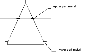
Wooden framed boxes and crates weighing 5 metric tons or more shall be reinforced with metal for protection of the package during sling and lifting operation as shown in Table 1 and Figure 1.
Table 1 -- Reinforcing Metal
|
Thickness of Reinforcing Metal |
||
|
Gross Weight |
Lower Part |
Upper Part |
|
up to 15 tons |
4.5 mm |
3.2 mm |
|
15 tons to 30 tons |
9.0 mm |
4.5 mm |
|
over 30 tons |
12.0 mm |
4.5 mm |
Figure 1 - Location of Reinforcing Metal
Any machine-finished part that is secured/blocked for shipment using wood chocks or wood framing shall be separated from the wood using moisture preventive material to prevent penetration of moisture through the wood to the metal surface.
The ratio of openings in the crates shall be limited to 35 percent or less.
3.5.2 Wooden Boxes (Non-framed)
Wooden boxes shall be constructed based on Attachment 9. Wooden boxes shall be used for equipment and materials not more than 1,000 kg in weight or five (5) cubic meters in measurement. The use of nonframed wooden boxes requires the prior approval of Company.
Main members of each wooden box shall conform to Attachments 4 and 10. Wooden boxes may be assembled based on the vendor's standard. The requirements for waterproof or moisture-proof protection are the same as for framed boxes.
3.5.3 Wood and Plywood Specifications
The allowable working strength of wood is 116 kg/cm² or more on flat, and 89 kg/cm² or more on end. The species of wood that provide such strength are Douglas fir, Western hemlock, larch, etc.
Figure 2 - Strength of Wood

3.5.4 Wood Dimension
Wood dimensions shall conform to Table 2.
Table 2 -- Wood Dimensions
|
Nominal Size |
Minimum Size |
Nominal Size |
Minimum Size |
|
12 mm |
10 mm |
70 mm |
70 mm |
|
15 |
12 |
90 |
84.5 |
|
18 |
15 |
100 |
94.5 |
|
21 |
18 |
120 |
111 |
|
24 |
21 |
150 |
143.5 |
|
30 |
25 |
180 |
173 |
|
45 |
40 |
210 |
202 |
|
50 |
46 |
210 or more |
Nominal size - 8 |
|
60 |
55 |
210 or more |
Nominal size - 8 |
3.5.5 Allowable Tolerance on Plywood Thickness
The allowable tolerance on thickness of plywood shall conform to Table 3.
Table 3 -- Plywood Thickness Tolerance
|
Nominal Size (mm) |
Allowable Tolerance (%) |
|
less than 5 mm |
± 5% |
|
5 to 10 |
± 4 |
|
10 to 20 |
± 3 |
|
20 or more |
± 2 |
3.6 Skid Mounting Construction
3.6.1 Lengthy equipment, such as columns, vessels and heat exchangers, may be shipped bare on skid mounting. They shall be fixed by steel/wire rope, steel bands, or flat bars as shown in Attachment 11.
Skids and their position etc. may conform to vendor's standard to ensure safe handling for long-distance transportation.
However, the vendor shall apply skids based on the requirements in this subsection and shall submit shipping sketches to RE&C Ploiesti for prior approval.
3.6.2The maximum span of skids shall be limited to eight (8) meters. The number of skids shall conform to Table 4.Table 4 -- Number of Skids
|
L W |
W |
||||
|
up to 30 |
30 to 50 |
50 to 100 |
100 to 200 |
over 200 |
|
|
up to 10 |
2 |
2 |
2 |
2 |
2 |
|
10 to 20 |
2 |
3 |
4 |
4 |
4 |
|
20 to 30 |
2 |
3 |
4 |
4 |
4 |
|
30 to 40 |
3 |
3 |
4 |
4 |
4 |
|
40 to 50 |
4 |
4 |
4 |
4 |
6 |
|
over 50 |
4 |
4 |
6 |
6 |
6 |
W = Gross weight (ton)
L = Length of equipment (meter)
3.6.3 Skid size shall be determined as shown in Figure 3.
Figure 3 - Skid Shape
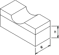
W : H = 1 : 1½ (maximum)
3.6.4 Provide each item with lifting and slinging points that will distribute the load equally and will keep the item in a stable, horizontal position when lifted by one hook.
Stress calculations and minimum sling lifting angles must be furnished.
3.6.5 Cover all surface areas of the item, which may come in contact with the slings during lifting, with wooden hurdles. This will prevent scratches, dents and other damage. Hurdle dimensions are given in Table 6.
Table 6 -- Hurdle Size
|
Net weight |
less than 20 tons |
less than 30 tons |
over30 tons |
|
Thickness |
minimum 30 mm |
minimum 45 mm |
minimum 60 mm |
|
Width |
standard 90 mm |
||
|
Length |
standard 800 mm, minimum 600 mm |
||
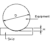
3.6.6 Minimum depth scooped out (H) of skid is as shown in Table 7 and Figure 4.
Table 7 -- Scooped-out depth of skid
|
Diameter (D) |
H |
|
1 m or less |
100 mm |
|
2 m or less |
200 mm |
|
3 m or less |
270 mm |
|
4 m or less |
360 mm |
|
5 m or less |
450 mm |
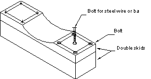
3.6.7 When using double skids, the skids shall be bolted as shown in Figure 5.
Figure 5 - Double Skid
3.6.8 The clearance between the lowest parts of equipment and ground level shall be not less than 100 mm.
3.6.9 Cushioning materials, such as polyethylene sterol, shall be applied between the "skids and body" and between "the body and steel band or flat bar". Steel wire rope shall be vinyl-coated.
3.6.10 For saddled equipment, such as horizontal vessels or heat exchangers, wooden skids under the base plates shall be as shown in Attachment 12.
3.6.11 Important Notes :
The general requirements for transportation skids/saddles and other lifting devices are as follows:
3.6.12 For ocean carriage:
Vendor shall warrant that equipment is suitable for handling with ship's/shore lifting gear.
Equipment shall be fitted with suitable lifting lugs or other adequate means of lifting and shall be properly marked as where to place the slings to enable ocean carrier to lift the cargo in equilibrium, whereby center of gravity shall be indicated.
All lifting devices, such as beams, spreaders, lugs, etc., as supplied by vendor shall be certificated by an officially recognized authority and acceptable to the authorities in loading and discharge ports.
Cradles and or supports for items of equipment - which by its nature - require the use of same, shall be suitable for ocean transportation in design, strength and number. Equipment shall be fitted with sufficient locations to attach lashing wires.
3.6.13 For overland transportation :
Transportation saddles attached to long-length items of equipment are providing the connection between the load and the trailer, and the load itself is providing the chassis between the trailers. Therefore, it is necessary for the transport saddles to be adequately secured to the load and, in turn, to be of sufficient substance to withstand horizontal forces required to pull the trailers in any direction.
Depending on the obstacles, as encountered, from port of unloading to construction site, the location of saddles may be a key factor.
3.7 Bundle
3.7.1 Pipes, steel structures etc., may be bundled as shown in Attachment 13 with steel wire or steel bands at both ends and at center. The maximum spacing of bands shall be limited to 1,500 mm to with stand sling load. The minimum diameter of steel wire is 3.4 mm, and the minimum thickness of steel bands is 0.7 mm.
3.7.2 Semi-fireproof buffer material, such as polypropylene cloth, shall be applied between steel bands and material to prevent the steel bands from directly touching the material, unless vinyl-coated steel wire is used. Both ends shall be covered with polypropylene cloth before they are bundled. The minimum length of cover is 30 cm (Attachment 13).
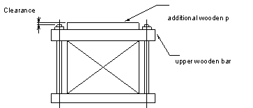
3.7.3 For a wooden bundle, additional wooden pieces shall be fixed to each upper wooden bar to prevent the bolts' ends from damaging the stacked cargo.
Figure 6 - Upper Wooden Bar
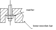
Spot facings shall be applied to lower wooden bars to recess and protect bolt ends as shown in Figure 7.
Figure 7 - Spot Facing
3.8 Bare
For materials to be shipped bare (without packing), refer to Attachment 14.
Any projection of equipment and materials at sling points shall be protected enough to prevent damage by sling wires.
When transporting vehicles, the following protective measures shall be taken into consideration:
-
Minimize the required quantity of fuel oil, cooling water, and lubricating oil
-
Disconnect the battery
-
Remove the hook of a forklift, crane accessories, canvas roof of any truck and pack them individually; securely fasten accessories to the operator's seat if possible
-
Do not remove signals or spare tires
-
Adequately grease the wheels.
3.9 Shrink Wrapping
Fire bricks, castable and insulating materials may be shrink-wrapped based on Appendices 15 and 16. However, shrink-wrapped cargo may be prohibited for certain projects. Vendors shall receive prior approval from Company Procurement.
The maximum weight of each shrink-wrapped package shall be limited to 1,400 kgs. Pallets shall be used for shrink-wrapped packages as shown in Attachment 17. The pallet dimensions are as given in Table 8.
Table 8 -- Pallet Dimensions
|
Stringer |
Upper Layer |
Under |
||
|
Net Weight |
No. |
Size (H x W)mm |
Size (W x T) mm |
|
|
£ 500 kg |
3 |
90 x 45 |
Edge Board 120 x 15 Deck Board 100 x 15 |
90 x 24 |
|
£ 1,000 kg |
3 |
90 x 45 |
Edge Board 120 x 18 Deck Board 100 x 18 |
90 x 24 |
|
£ 1,400 kg |
3 - 4 |
90 x 45 |
Edge Board 150 x 21 Deck Board 120 x 21 |
90 x 24 |
Two layers of films shall be used. Polyethylene film to cover the material shall be as given in Table 9.
Table 9 -- Covering Film
|
Net Weight |
Film Thickness |
|
500 kg or less |
0.15 mm |
|
1,000 kg or less |
0.20 mm |
|
1,400 kg or less |
0.22 mm |
For heavy cargo, such as fire brick, framed shrink-wrapped packages shall be as shown in Attachment 15. Each member shall have the strength to bear the load of three piles of shrink-wrapped packages.
For light cargo, such as castable and insulating materials, non framed shrink-wrapped packages may be as shown in Attachment 16.
3.10 Packing List
A packing list in a waterproof envelop shall be fixed to both the outside and inside of each package. The packing list shall show only those items actually being shipped. Items that were previously shipped or items to be shipped in the future, must not be included.
3.11 Minimum and Maximum Package Size
3.11.1 Minimum Weight and MeasurementThe vendor shall pack the consignment generally into packages not less than 200 kgs in weight and 0.7 cubic meters in size to avoid theft and loss during transportation. If it is impossible to follow these limits for technical reasons, the vendor shall obtain RE&C’s Ploiesti Office agreement.
In general, packing shall be accomplished to result in the least possible shipping displacement of each shipping unit.
3.11.2 Transportation LimitsDue to the limits of local inland transportation, the vendor shall not prepare a package exceeding the following limits:
|
(1) Length |
(meters) |
} |
HOLD |
|
(2) Width |
(meters) |
} |
Depending |
|
(3) Height |
(meters) |
} |
on |
|
(4) Gross weight |
(kg) |
} |
Project |
Extra costs caused by the vendor's nonconformance to these limits shall be born by or backcharged to the vendor.
3.12 Transportation Aids
3.12.1 Special Traverse
Vendors who supply a considerable amount of steel plates for tankage or very large equipment, such as an air-cooled heat exchanger, shall provide the special lifting traverses to be used at both the ports of loading and discharging. These costs shall be born by the vendor.
3.12.2 Lifting Lugs
The vendor who supplies heavy equipment, package type boilers, or equipment with an eccentric center of gravity shall provide lifting lugs on the equipment itself. These costs shall be born by the vendor.
4. Marking
All items and their packaging shall be clearly marked in order that they will be readily identifiable and traceable to the accompanying and other applicable documentation.
4.1 Materials
All items will be worked so that the marking will not be lost or substantially degraded during handling, shipping, storage, installation or operation.
Marking will be in accordance with the relevant specification or standard requirements.
Equipment shall, in addition to the standard marking instructions, carry a nameplate that will be in accordance with the nameplate drawing.
With the exception of any item manufactured from austenitic stainless or nickel alloy steels, any item with a wall thickness over 5 mm shall be legibly hard die-stamped on a painted background (for pipes at 25 cm from one end). For small diameter items, the stamping may be ringed or circled in the prescribed paint color.
Only low-stress stamps shall be used for hard die-stamping.
For austenitic stainless or nickel alloy steels and any items below 5 mm wall thickness, marking shall be by stencil using a water insoluble ink free from substances such as metallic pigments, sulfur, sulphides or chlorides that could attack or harmfully affect the materials.
Marking may also be carried out by using a "micro-etcher" or engraver as an alternative to a stencil, such marking being on or surrounded by the prescribed paint color.
The stamping/marking shall include:
- Manufacturer's symbol (stamp to be identical to symbol on the material certificate)
- Material specification and grade
- Charge, batch, heat and/or slab number
- Heat treatment charge or furnace charge reference number where applicable
- Heat treatment symbol where applicable
- Nondestructive testing symbol or code where applicable
- Size and schedule.
Notes:
-
Where the size of fitting does not permit complete marking, the identification marks may be omitted in the reverse order indicated above. Each item, however, shall be marked to the extent necessary to positively identify the items against its related material test certificate.
-
For pipes 1½ inch (40 mm) and smaller, the required marking shall be diestamped on a durable tag fixed to the bundle.
- For each lot of fittings 1½ inch (40 mm) and smaller, each package shall be provided with a label or plate of identification, firmly attached to the lot, stating at least:
- Purchase order number
- Charge or batch number
- Manufacturer's name.
4.2 Marking Specification for Export Shipment
This section covers special warning tag requirements for prohibition of any welding on the equipment after its delivery at shop.
The vendor who supplies the equipment, such as pressure vessels, heat exchangers etc., shall attach to each equipment the warning tag with the following descriptions by stenciling in red color:
"Any welding is prohibited during transportation from the factory shipment to job site".
The warning tag shall be attached on at least two places to each equipment as shown in Attachment 21.
4.2.1 Shipping Mark
Every package shall be clearly marked in accordance with the project specifications, the main shipping mark being clearly stenciled.
When the mark is stenciled directly onto the surface of the equipment, such as a column, vessel or heat exchanger, a color in contrast to the equipment shall be used. If the package does not allow enough space for the main shipping mark, three or more metal labels of appropriate size showing the same information shall be firmly affixed to the package. The mark shall also be shown on the packing list and commercial invoice.
The letter size in the main shipping mark shall be determined according to the package size but shall be clearly legible so that the mark may be identified from a distance. The recommended sizes are as given in Table 10.
Table 10 -- Letter Size of Shipping Mark
|
Package Length |
Letter Size (H x W) |
|
less than 1000 mm |
25 mm x 20 mm |
|
1000 to 3000 mm |
40 mm x 30 mm |
|
3000 to 5000 mm |
50 mm x 40 mm |
|
over 5000 mm |
60 mm x 50 mm |
For bare or bundled cargo on which stenciling is impossible, each package shall have at least three metal labels with the printed shipping mark. The metal labels shall be engraved on each sheet using moisture-proof paint or indelible ink.
4.2.2 Auxiliary Marks
Any auxiliary marks shall be clearly stenciled as prescribed for each project. Unnecessary or wrong marks may cause trouble during cargo handling and customs clearance. Therefore, marks other than those required shall not be applied or stenciled on any package.
-
Care mark:
To avoid breakage, care marks shall be stenciled where appropriate. The size of the marks shall be determined depending on the package size.
-
Sling mark, center balance mark and approximate weight:
To avoid cargo handling delays and prevent accidents, sling marks, center balance marks and the approximate weight shall be stenciled at the correct positions and in a proper manner after the vendor has actually lifted each package.
-
Color band and corner color:
To avoid cargo handling delays at the jobsite, color bands and corner color shall be stenciled on each package if specified. The color, size and location shall conform to the shipping instruction for each project.
5. Attachments
click here for pdf file- Packing Style Criteria
- Wooden Framed Box (with Skid Base)
- Wooden Framed Crate (with Skid Base)
- Allowable Load for One Load-Bearing Floor Member (Uniformly Distributed Load)
- Center-to-Center Spacing of Top Joist
- Framing for Lumber Sheathing
- Framing for Plywood Sheathing
- Ventilation System
- Wooden Box (with Skid Base)
- Main Member Size for Wooden Box
- Typical Drawing of Skid-Mounted Equipment
- Marking Method of Skid-Mounted Equipment
- Steel Bundle and Wooden Bundle
- Bare, Metal Drum and Wooden Drum
- Framed Shrink Wrapping
- Non-Framed Shrink Wrapping
- Pallet for Shrink Wrapping
- Marking Specification for Boxes, Crates and Shrink-Wrapped Packages
- Position of Shipping Mark, Care Mark and Center Balance
- Care Mark, Center Mark and Sling Mark
- Position of Warning Tags

