
")
Table of Contents
1. Tankage Grouping
Tankage area will be subdivided into various groups determined by the contents of the tanks and the relative shape and area of the plot available, access and fire fighting must also be considered. See below table API tank size for layout purposes.
2. Classification of Crude Oil and Its Derivatives
Crude oil and its derivatives are potentially hazardous materials. The degree of the hazard is determined essentially by volatility and flash point.
The Institute of Petroleum has specified the following classes:
| Class 0 | Liquified petroleum gases (LPG) | |
| Class I | Liquids which have flash points below 21 oC | |
| Class II | (1) | Liquids which have flash points from 21 oC upto and including 55 oC handled, below flash point |
| Class II | (2) | Liquids which have flash points from 21 oC upto and including 55 oC handled, at or above flash point |
| Class III | (1) | Liquids which have flash points above 55 oC upto and including 100 oC handled, below flash point |
| Class III | (2) | Liquids which have flash points above 55 oC upto and including 100 oC handled, above flash point |
| Unclassified. | Liquids with flash points above 100 oC |
For further information see IP refinery safety code part 3.
3. Tankage Layout
3.1 General
The layout of tanks, as distinct from their spacing, should always take into consideration the accessibility needed for fire-fighting and the potential value of a storage tank farm in providing a buffer area between process plant and public roads, houses, etc. , for environmental reasons.
The location of tankage relative to process units must be such as to ensure maximum safety from possible incidents.
Primarily requirements for the layout of refinery tanks farms are summarised as follows.
- Inter tank spacings and separation distances between tank and boundary line and tank and other facilities are of fundamental importance. (See 3.2) .
- Suitable roadways should be provided for approach to tank sites by mobile fire fighting equipment and personnel.
- The fire water system should be laid out to provide adequate fire protection to all parts of the storage area and the transfer facilities.
- Bunding and draining of the area surrounding the tanks should be such that a spillage from any tank can be controlled to minimise subsequent damage to the tank and its contents. They should also minimise the possibility of other tanks being involved.
- Tank farms should preferably not be located at higher levels than process units in the same catchment area.
- Storage tanks holding flammable liquids should be installed in such a way that any spill will not flow towards a process area or any other source of ignition.
3.2. Spacing of Tanks for LPG Stocks of Class 0
| Factor | Recommendations for LPG Stored in Pressure Tanks | |
| 1. Between LPG pressure storage tanks | One quarter of the sum of the diameters of the two adjacent tanks. | |
| 2. To Class I, II, or III product tanks. | 15 M from the top of the surrounding Class I, II or III product tanks. | |
| 3. To low pressure refrigerated LPG tanks. | One diameter of the largest low pressure refrigerated storage tanks but not less than 30 M. | |
| 4. To building containing flammable material e.g. filling shed, storage building. | 15 M | |
| 5. To boundary or any fixed source of ignition. | Related to water capacity of tank as follows : | |
| Capacity Up to 135 cu.M Over 135 to 565 cu.M Over 565 cu.M |
Distance 15 M 24 M 30 M |
|
The distance given in the above table are minimum recommendations for aboveground tanks and refer to the horizontal distance in plan between the nearest point on the storage tank and a specified feature, e.g. an adjacent storage tank, building, boundary. The distances are for both spherical and cylindrical tanks.
3.3 Bunding and Grouping of LPG Tanks
The provision of bunds around LPG pressure storage tanks is not normally justified.
Separation kerbs, low to avoid gas traps, maximum 600 mm high, may be located to prevent spillage reaching important areas, e.g. pump manifold area, pipe track.
Ground under tanks should be graded to levels which ensure that any spillage has a preferential flow away from the tank.
Pits and depressions, other than those which have been provided as catchment areas, should be avoided to prevent the forming of gas pockets.
Pressure storage tanks for LPG should not be located within the bunded enclosures of Class I, II or III product tankage or of low pressure refrigerated LPG tankage.
The layout and grouping of tanks, as distinct from spacing, should receive careful consideration with the view of accessibility for fire fighting and the avoidance of spillage from one tank flowing towards the other tank or towards a nearby important area.
3.4 Spacing of Tanks for Low Pressure Refrigerated LPG Storage Class 0
| Factor | Recommendations for Low Pressure Refrigerated LPG Storage |
| 1. Between refrigerated LPG storage tanks | One half of the sum of the diameters of the two adjacent tanks. |
| 2. To Class I, II, or III product tanks. | One diameter of the largest refrigerated storage tank but not less than 30 M. |
| 3. To pressure storage tanks. | One diameter of the largest refrigerated storage tank but not less than 30 M. |
| 4. To process units, office building, work-shop, laboratory, warehouse, boundary, or any fixed source of ignition. | 45 M |
The distance given in the above table are minimum recommendations and refer to the horizontal distance in plan between the nearest point on the storage tank and a specified feature, e.g. an adjacent storage tank, building, boundary.
3.5. Bund or Impounded Basin for Refrigerated LPG Storage
A bund should be provided around all low pressure tanks containing refrigerated LPG. The tank should be completely surrounded by the bund, unless the topography of the area is such, either naturally or by construction, that spills can be directed quickly and safely, by gravity drainage and diversion walls if required, to a depression or impounding basin located within the boundary of the plant.
Bunds should be designed to be of sufficient strength to withstand the pressure to which they would be subjected if the volume within the bunded enclosure were filled with water. The area within the bund, depression, or impounding basis should be isolated from any outside drainage system by a valve, normally closed unless the area is being drained of water under controlled conditions.
Where only one tank is within the bund, the capacity of the bunded enclosure, including the capacity of any depression or impounding basis, should be 75 per cent of the tank capacity. Where more than one tank is within the main enclosure, intermediate bunds should be provided, so as to give an enclosure around each tank of 50 per cent of the capacity of that tank, and the minimum effective capacity of the main enclosure, including any depression or impounding basin, should be 100 per cent of the capacity of the largest tank, after allowing for the volume of the enclosure occupied by the remaining tanks. It is desirable for the required capacity to be provided with bunds not exceeding an average height of 6 foot as measured from the outside ground level.
The area within the bund should be graded to levels which ensure that any spillage has a preferential flow away from the tank.
No tankage other than low pressure tankage for refrigerated LPG should be within the bund. The layout and grouping of tanks, as distinct from spacing, should receive careful consideration with the view of accessibility for fire fighting.
3.6 Piping Installation and Flexibility
Liquid and vapour pipelines should have adequate flexibility to accommodate any settlement of tanks or other equipment, thermal expansion or other stresses that may occur in the pipe work system.
Precaution must be taken to prevent drain or sample valves freezing in the open position. The flow diagram will indicate the type of double valving to be installed, with a minimum distance between the valves of 1 meter. Do not allow liquid traps in vent lines.
3.7 Spacing of Tank for Petroleum Stocks of Classes I, II and III (2) .
| Factor | Type of Tank Roof | Recommended Minimum Distance |
| 1. Within a group of small tanks | Fixed or Floating | Determined solely by construction / maintenance operational convenience |
| 2. Between a group of small tanks or other larger tanks. | Fixed or Floating | 10 M minimum, otherwise determined by the size of the larger tanks (see 3 below) |
| 3. Between adjacent individual tanks (other than small tanks). | (a)Fixed | Half the diameter of the larger tank, but not than 10 M and need not be more than 15 M. |
| (b)Fixed | 0.3 times the diameter of the larger tank, but not less than 10 M and need not be more than 15 M. (In the case of crude oil tankage this 15 M option does not apply) | |
| 4. Between a tank and the top of the inside of the wall of its compound | Fixed or Floating | Distance equal to not less than half the height of the tank. (Access around the tank at compound grade level must be maintained) |
| 5. Between any tank in a group of tanks and the inside top of the adjacent compound wall. | Fixed or Floating | |
| 6. Between a tank and a public boundary fence. | Fixed or Floating | Not less than 30 M |
| 7. Between the top of the inside of the wall of a tank compound and a public boundary fence or to any fixed ignition source. |
-
|
Not less than 15 M |
| 8. Between a tank and the battery limit of a process plant. | Fixed or Floating | Not less than 30 M |
| 9. Between the top of the inside wall of a tank compound and the battery limit of a process plant |
-
|
Not less than 15 M |
The table above gives a guidance on the minimum tank spacing for Class I, II and III (2) storage facilities, the following points should be noted.
- Tanks of diameter up to 10 M are classed as small tanks
- Small tanks may be sited together in groups, no group having an aggregate capacity of more than 8000 m3. Such a group may be regarded as one tank.
- Where future changes of service of a storage tank are anticipated the layout and spacing should be designed for the most stringent case.
- For reasons of fire fighting access there should be no more than two rows of tanks between adjacent access roads.
- Fixed roof with internal floating covers should be treated for spacing purposes as fixed roof tanks.
- Where fixed roof and floating roof tanks are adjacent, spacing should be on the basis of the tank(s) with the most stringent conditions.
- Where tanks are erected on compressible soils, the distance between adjacent tanks should be sufficient to avoid excessive distortion. This can be caused by additional settlements of the ground where the stressed soil zone of one tank overlaps that of the adjacent tank.
- For Class III (1) and unclassified petroleum stocks, spacing of tanks is governed only by constructional and operational convenience. However, the spacing of Class III (1) tankage from Class I, II or III (2) tankage is governed by the requirements for the latter.
- For typical tank installation, illustrating how the spacing guides are interpreted see below figures.
For details of a typical vertical tank foundation see below figures.
3.8 Tank Farm Piping and Layout
Pipelines connected to tanks should be designed so that stresses imposed are within the tank design limits. The settlement of the tank and the outward movement of the shell under the full hydrostatic pressure should be taken into account. The first pipe support from the tank should be located at a sufficient distance to prevent damage both to the line and to tank connections. Consideration may be given to installing spring supports near to tank connection for large bore pipework.
As large diameter tanks have a tendency to settle on their foundations, provision must be made in the suction and filling piping to take care of tank settlement. This may require the use of expansion joints, victaulic couplings, or a lap joint flange installed as shown in see below figure.
The following note must be added to all piping drawings containing storage tanks:
“All piping must be disconnected from tank during hydrostatic test of storage tank”
The number of pipelines in tank compounds should be kept to a minimum. They should be routed in the shortest practicable way to the main pipe tracks located outside the tank compounds, with adequate allowance for expansion.
Flexibility in piping systems may be provided through the use of bends, loops or offsets. Where space is a problem suitable expansion joints of the bellows type may be considered for installation in accordance with manufacturer’s design specifications and guides. These expansion joints should be used only in services where the fluid properties are such that plugging of the bellows cannot occur. They should be anchored and guided, should not be subjected to torsional loads, and should be capable of ready inspection.
Tank farm piping should preferably be run above ground on concrete or steel supports. Ground beneath piping should be so graded as to prevent the accumulation of surface water or product leakage. Manifolds should be located outside the tank bunds.
Piping should pass over earth bund walls, however, if this is impossible, a suitable pipe sleeve will be provided to allow for expansion and possible movement of the lines. The annular space should be properly sealed. Likewise lines passing through concrete bund walls will be provided with pipe sleeves.
Pedestrian walkways should be provided to give operational access over ground level pipelines.
Pipelines should be protected against uneven ground settlement where they pass under roadways, railways or other points subject to moving loads.
Buried pipelines should be protected externally by corrosion preventing materials, or by cathodic means.
Routes of buried pipelines should be adequately marked above ground and recorded.
Pipe racks carried across paths or roads should have adequate clearance from grade. Adequate access stairways or ladders and operating platforms should be provided to facilitate operation and maintenance at tanks. Tanks may be interconnected at roof level by bridge platforming.
All nozzles, including drains on a tank shell, should have block valves adjacent to the tank shell or as close as practicable.
3.9 Tank Bund Compound Capacities
Above ground tanks for Class I, II (1), II (2) and III (2) petroleum liquids should be completely surrounded by a wall or walls. Alternatively, it is acceptable to arrange that spillage or a major leak from any tank are directed quickly and safely by gravity to a depression or impounding basis at a convenient location.
The distance between the edge of the impounding basin and the nearest tank or the inside top of the nearest bund wall should be a minimum of 30 M. The distance between the edge of the basin and road fence battery limit of a process plant should not be less than 15 M.
The height of the bund wall as measured from outside ground level should be sufficient to afford protection for personnel when engaged in fire fighting and the wall should be located so that a reasonably close approach can be made to a tank fire to allow use of mobile fire fighting equipment. Access roads over bund walls into very large compounds are helpful in certain fire situations.
Separate walls around each tank are not necessary, but the total capacity of the tanks in one bunded area should be restricted to the following maximum figures:
| Single tanks | No restriction |
| Groups of floating roof tanks | 120,000 m3 |
| Groups of fixed roof tanks | 60,000 m3 |
| Crude tanks | Not more than two tanks of greater individual capacity than 60,000 m3 |
The figures for b. and c. may be exceeded for groups of not more than three tanks, where there can be no risk of pollution or hazard to the public.
Intermediate walls of lesser height than the main bund walls may be provided to divide tankage into groups of a convenient size so as to contain small spillages and act as fire breaks.
Buried, semiburied or mounded tanks need not be enclosed by a bund wall except when they are located in ground higher than the surrounding terrain. However, consideration should be given to the provision of small bund walls around associated tank valves.
The net capacity of the tank compound should generally be equivalent to the capacity of the largest tank in the compound. However, a reduction of this capacity of 75% will provide reasonable protection against spillage and may be adopted where conditions are suitable (e.g. where there can be no risk of pollution or hazard to the public). The net capacity of a tank compound should be calculated by deducting from the total capacity a. the volume of all tanks, other than the largest, below the level of the top the compound wall and b. the volume of all intermediate walls.
A low wall which need not be more than 0.5 m high, should be constructed for Class III (1) and unclassified petroleum product tankage where conditions are such than any spillage or leakage could escape from the installation and cause damage to third party property drainage systems, rivers or waterways.
Where there is a possibility that tanks storing these products may be in the future required for Class I, II (1) or III (2), then the compound walls should be suitable for this potential situation.
4. Pump Areas
Pumps will be located outside bund areas. The vessels practice is to group the pumps into bays. Keep the suction lines as short as practical. The discharge piping will run on low level tracks to the process or loading areas. These tracks will usually pass under roads in culverts, but may pass over on a pipe bridge. Long pipe runs may require expansion loops to provide flexibility. Consult with stress section.
5. Fire Protection
For storage areas the major fire fighting effort will be provided by mobile equipment laying down large blankets of foam and/or applying large volumes of water for cooling purposes.
It is essential to provide a good system of all weather roads to facilitate the transfer of fire protection materials and equipment to the scene of the fire. These roads must be of adequate width and, wherever possible, with no deadends.
It is important in the siting of tanks, bund walls and access roads that the tanks can be protected by cooling water or foam appliances situated outside the compound walls. Account must be taken of the height of the tank and the possible need to cool the roof or project foam on to a tank.
Dry risers for foam may be provided to the top of storage tanks with their connections adjacent to access roads, fixed monitors may also be employed. The flow diagram will define the system to be employed.
6. Road and Rail Loading Facilities
Road and rail loading facilities are usually associated with storage area. The safe location of these in relation to storage tanks is laid down in section 3.7.
The road or railcar will be filled from a loading island, the supply lines will be either routed underground, or on an overhead pipe bridge. Check for clearances.
Below figures show such installations.
It has become common practice to provide a vapour collection system for the safe removal of vapours during the loading process. This system would employ unloading arms which are connected to a collection system and piped to a vent stack at a safe location.
When laying out a loading area consideration must be given to the number of vehicles or rail cars per hour to be loaded. A suitable movement pattern must be established for incoming and outgoing vehicles or railcars. Weigh bridges will be required, the system of moving rail cars must be defined, building housing, operation offices and facilities for drives etc. , must be provided.
Figures:
API TANK SIZE - FOR LAYOUT PURPOSE
Based on API650
| Capacity Approximately | Diameter | Height | |
| US Barrels | CU Meters | Meters | Meters |
|
500
|
75
|
4.6
|
4.9
|
|
1.000
|
150
|
6.4
|
4.9
|
|
1.500
|
225
|
6.4
|
7.3
|
|
2.000
|
300
|
7.6
|
7.3
|
|
3.000
|
450
|
9.2
|
7.3
|
|
4.000
|
600
|
9.2
|
9.3
|
|
5.000
|
750
|
9.2
|
12.2
|
|
6.000
|
900
|
9.2
|
14.6
|
|
7.000
|
1050
|
12.2
|
9.9
|
|
9.000
|
1350
|
12.2
|
12.2
|
|
10.000
|
1500
|
12.8
|
12.2
|
|
12.000
|
1800
|
12.8
|
14.6
|
|
15.000
|
2250
|
14.6
|
14.6
|
|
20.000
|
3000
|
18.3
|
12.2
|
|
30.000
|
4500
|
22.3
|
12.2
|
|
40.000
|
6000
|
26.0
|
12.2
|
|
50.000
|
7500
|
27.5
|
14.6
|
|
90.000
|
12000
|
36.6
|
12.2
|
|
100.000
|
15000
|
41.0
|
12.2
|
|
120.000
|
18000
|
41.0
|
14.6
|
|
140.000
|
21000
|
49.8
|
12.2
|
|
180.000
|
27000
|
54.9
|
12.2
|
|
200.000
|
30000
|
54.9
|
14.6
|
|
300.000
|
45000
|
61.0
|
17.0
|
|
450.000
|
60000
|
73.2
|
17.0
|
|
600.000
|
90000
|
91.5
|
14.6
|
|
800.000
|
100000
|
105.0
|
14.6
|
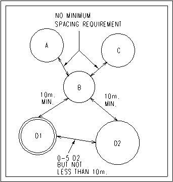
Figure 1.
TANKS A, B, C ARE FIXED OR FLOATING ROOF SMALL TANKS (LESS THAN 10 m. DIAMETER) WITH A TOTAL CAPACITY OF LESS THAN 8000 m3; NO INTER-TANK SPACING REQUIREMENTS OTHER THAN FOR CONSTRUCTION / OPERATION / MAINTENANCE CONVENIENCE. TANKS D1 & D2 ARE TANKS WITH DIAMETERS GREATER THAN 10 m., & WITH DIAMETER OF D2 GREATER THAN D1.
Inter-tank spacings between small and larger tanks.
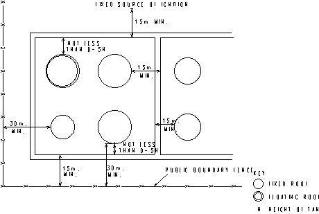
Tank and compund wall distances from typical features.
Figure 2.
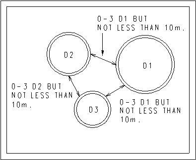
FLOATING ROOF TANKS OF DIAMETER D1 D2 D3 GREATER THAN 10 m. WITHIN THE SAME COMPUND. D1 GREATER THAN D2 & D2 GREATER THAN D3.
Figure 3.
Inter-tank spacing for floating roof tanks (greater than 10 m diameter).
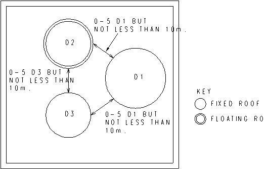
FIXED & FLOATING ROOF TANKS WITHIN THE SAME COMPOUND. D1 GREATER THAN D2, D2 EQUAL TO D3.
Figure 4.

Lap joint Flange Detail for Tank Settlement
Figure 5.
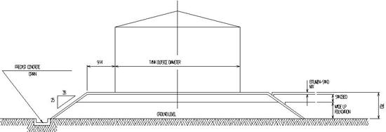
Foundation for vertical tank
Based on BS2654
Figure 6.