
")
Table of Contents
- General
- Types of Cooling Towers
- Cooling Tower Location
- Water Makeup
- Trash Screen and Gate
- The Pump Basin
- Suction Piping
- Pump Priming
- Bypass
- Chemical Dosing
- Cooling Tower Structure
- Winterizing
1. General
Cooling water is an essential service in any chemical plant or refinery and control of temperature plays a critical part in any plant process. Therefore, any water used for cooling picks up heat from the medium being cooled, and must itself be cooled before being recirculated.
The cooling tower enables this water cooling to be carried out.
Regardless of type of tower selected there is always a reservoir of water at the base, from which water is drawn and pumped around the plant. It is returned via a header pipe, back to the top of the tower.
The water is then dispersed over the whole area of the tower by means of wooden slats or sprinkler nozzles. This breaks the water up into fine droplets similar to rain, thus exposing a greater surface area and enabling cooling to be much more effective. The cooled water is collected in the basin under the tower and is ready for reuse.
2. Types of Cooling Towers
There are two types of towers essentially used in refineries and chemical plants:
a. Natural draft (Venturi/Chimney type)
b. Induced draft (Box type)
2.1 Natural Draft Cooling Towers
The natural draft type is not often used, and is normally only used when the contours of the ground provide a high position on which they can be located. The higher position giving unimpeded wind area.
2.2 Induced Draft Cooling Towers
Induced draft cooling towers are furnished in two types, based on the direction of air flow relative to the water to the water through the tower:
a. Crossflow
b. Counterflow
In the crossflow cooling tower, the sides are entirely open, and air passed through the sides to a central plenum chamber, across the downward flow of water, and exhausted through the top of the structure by one or more fans. Some characteristics of crossflow towers, compared to counterflow towers, are:
a. Contact surface is less effective.
b. Air flow quantity is greater.
c. Icing is more of a problem in winter months.
d. Fan horsepower may be higher.
The counterflow tower has straight enclosed sides, except for an air entrance near the bottom. Air is taken in at the bottom of the tower, rises countercurrent to the downward flow of water, and is exhausted at the top by means of one or more fans.
Some characteristics of counterflow towers, compared to crossflow towers are:
a. Lower air flow quantity.
b. Fan horsepower may be lower.
c. Generally lower fire protection cost.
d. Usually lower pumping height.
e. Frequently larger basin area.
3. Cooling Tower Location
A cooling tower is one of the larger items of equipment, in terms of ground area, that must be located on a site plan. Factors affecting the location of cooling towers, other than convenience to water supply and return are:
a. Prevailing wind
b. Noise
c. Access roads
3.1 Prevailing Winds
Cooling towers should be located with the small side towards the prevailing wind. The gives both long sides an equal intake of fresh air.
Cooling towers should not be downwind or adjacent to fired heaters, flare stacks or any heat producing items as these raise the ambient air temperature and will reduce the towers cooling efficiency.
3.2 Noise
Noise levels of larger cooling towers can be quite high and may become objectionable if the tower is located too close to continually occupied work areas such as offices and control buildings, etc.
3.3 Access Roads
Access is required for the essential maintenance of pumps, chemical dosing equipment and for handling of trash screens.
Cooling towers lose water by evaporation and entrainment (windage), resulting in a water spray and fog on the downwind side of the tower making any roads continually wet. This is a traffic hazard and can cause icing in winter.
In general, a minimum distance of 15 to 20 meters of clear area should be allocated for air movement about the tower.
4. Water Makeup
Water makeup to a cooling tower is necessary to replace the mechanical carryout of water droplets (windage), evaporation and the blowdown required to maintain a controlled solids buildup. Makeup water is usually added to the cooling tower basin.
Control of water level in the cooling tower basin is via a level instrument of some description. This should be located in the relatively still waters of the pump basin. If the instrument is of the level displacer type it should be housed in a “stillwell” located in the pump basin. This protects the instrument and dampens the turbulent water to give a smoothed water level for measurement.
Blowdown rate is dependent on the solids entering in the makeup water and the solids level to be maintained in the system. Blowdown is measured by a flow indicator at any point in the cooling water circulation system that may be convenient for its disposal to a sewer.
5. Trash Screen and Gate
A course filter or screen should be located between the cooling tower basin and pump basin to trap floating debris, and where it can be reached for regular cleaning.
A submerged orifice is a useful way of trapping floating debris. By keeping the opening a few centimeters off the tower basin floor, a mud trap is formed. This will prevent any silt or submerged objects from approaching the pump suction. The submerged opening is a convenient place for locating a means of isolating the pump basin from the cooling tower basin if required. This can be a proprietary penstock, or a simple wooden sluice gate.
6. The Pump Basin
The pump basin is an integral part of the tower basin, being cast directly onto one of its sides.
Where more than one pump draws from the same basin, the chamber should be shaped or provided with baffles to prevent one pump intake affecting the flow to the others. If any sudden changes in the flow path within the pump basin do occur, the pump intake should be located at least 5 pipe diameters downstream from them (see below figure).
7. Suction Piping
High losses at the pump intake can cause excessive turbulence that may adversely affect the pump’s performance. A “bellmouth” is the most effective way of reducing these losses and can simply be a concentric reducer, the large end being 1.5 x the diameter of the suction pipe diameter.
Clearance between the face of the “bellmouth” and the pump basin floor should be equal to the larger diameter of the “bellmouth”.
Another useful aid in reducing turbulence in the suction piping is to have at least 3 pipe diameters of straight pipe upstream of the pump suction flange. The submerged depth of the intake is not usually very critical, but a minimum of 1 m is good practice. For vertical immersed pumps, use the vendor’s recommendations. The suction line should rise positively to the pump flange to prevent air pockets. For double suction type pumps, bends in the horizontal should be greater than 3 pipe diameters upstream of the pump flange.
If the pump is mounted on its own plinth, a check should be made with the Civil Department for possibility of differential settlement of foundations. A flexible coupling may have to be installed in the suction piping.
8. Pump Priming
A pump cannot operate without being filled with liquid, therefore the minimum design liquid level in the pump basin should be above the casing of the pump. For pumps expected to startup automatically, this method is essential because there is no danger of the idle pump emptying itself. Vertical immersed pumps are also ideal for automatic standbys.
Where a pump must be above the minimum water level, other means are available for the priming of the pump but these should only be used with care. These include vent ejectors operated by steam, air or water, a foot-valve and a priming feed to the casing from a reliable water source.
9. Bypass
Within large pumps of high throughput, prolonged operation at too low a flow overheat the pump and water within, and may cause damage to the pump. Therefore, these pumps should be fitted with an open ended bypass from the discharge line back into the pump basin, terminating below the minimum water level. A means should be provided to prevent high velocity streams from disturbing the flow to the pump suction intakes.
10. Chemical Dosing
To inhibit the growth of algae, reduce scaling in the cooling water system, and to adjust the chemical balance of the water, inhibitors are added to the cooling water. If dosing is required, a Vendor’s water treatment package is usually used and the chemicals are fed into the pump basin near the sluice gate/trash screen. With chemical dosing the water treatment vendor’s recommendations should be followed.
11. Cooling Tower Structure
The cooling tower is usually a clad wooden structure constructed with a great number of light weight plastic components. This makes it susceptible to fire risks and a fire protection system should be considered.
This lightness of construction means that nozzle forces should be at a minimum and the flexibility of piping layout is of great importance.
Access should be adequate for the maintenance of the fan motors mounted on top of the structure and be sufficient to give access to any doors or hatches in the fan stacks and floor on top of the structures.
12. Winterizing
In cold climates steam injection is sometimes employed in the tower to prevent the pump basins from freezing. A steam header is run around the periphery of the tower basin, above the basin wall, and steam ejected via holes drilled into header, onto the water surface in the basin. Steam is also introduced into the pump basin via a sparger; this prevent the water freezing prior to being pumped into the cooling water system.
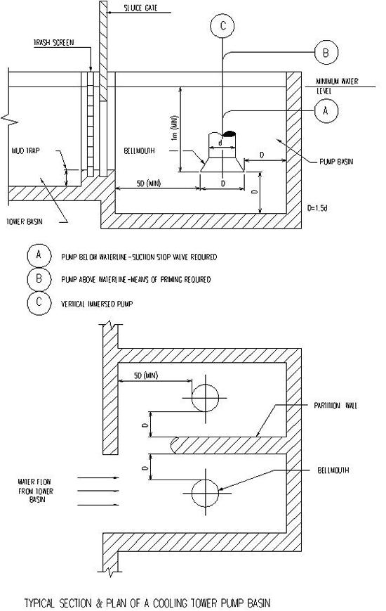
Figure 1.