Table of Contents
1. General
2. Materials and Methods
3. Items to be Fireproofed
4. Appendices
1. General
1.1 Scope
This specification covers the determination of fireproofing requirements on supporting elements for equipment and piping in a plant.
Fire Hazardous Areas shall be defined on a plotplan to further investigate the items requiring fireproofing.
The items to be fireproofed are listed in a summary, summarizing the fireproofing and their quantities for the relevant job.
It is important to establish the type and extent of fireproofing in an early phase of a job and to obtain the necessary approvals of parties involved.
1.2 Definitions
1.2.1 Fire Hazardous Area
A fire hazardous area is defined as the area affected by a potential source of fire, e.g., accidentally leaking flanges on ‘FIRE HAZARDOUS EQUIPMENT AND PIPING’.
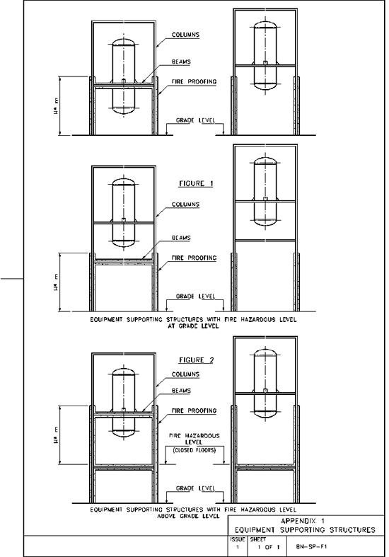
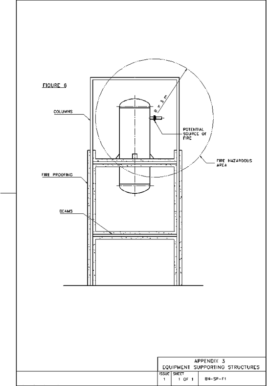
For hydrocarbon liquid leakage, forming a pool fire, the area consists of a cylindrical shape with a diameter of 6 m from the potential source of fire and a height of H*m above any FIRE HAZARDOUS LEVEL.
H*m in accordance with the loss prevention philosophy of the Client.
For hydrocarbon vapor leakage, forming a torch fire, the area consists of a spherical shape with a radius of 3 m from the potential source of fire. See Appendix 3, Fig. 6.
1.2.2 Fire Hazardous Equipment and Piping (Flammable Material)
Fire hazardous equipment and piping are defined as those containing ‘FLAMMABLE MATERIAL’ with the possibility of a sustained fire in case of leakage on e.g., flanges.
The following is considered as fire hazardous equipment and piping:
A piece of equipment and/or piping containing more than 0.5 m³ of ‘flammable material’.
Two or more pieces of equipment and/or piping containing together more than 0.5 m³ of ‘flammable material’ unless they are located more than 6 m apart.
Note: Internal combustion engines for pumps and compressors are considered non-fire hazardous.
1.2.3 Hazardous Equipment and Piping (Toxic)
Equipment and piping containing material that is toxic or otherwise dangerous to personnel.
1.2.4 Hazardous Equipment (by weight)
Heavy equipment as defined below:
· a piece of equipment with a total weight of 2500 kg or more;
· two or more pieces of equipment and an aggregate weight of 2500 kg or more, unless they are located more than 6 m apart.
1.2.5 Fire Hazardous Level
A fire hazardous level is defined as grade level or an elevated closed floor above which equipment and piping is located that is considered as fire hazardous.
1.2.6 Flammable Material
Flammable materials are defined as liquids with a flashpoint below 55°C, liquids being processed at a temperature above their flashpoint, or vapors of same nature.
1.3 Standards
1.3.1 The ASTM standards referred to herein may be obtained from ASTM (American Society for Testing and Materials), 1916 Race Street, Fax (215) 977-9679.
1.4 Regulations
1.4.1 This specification requires compliance with all applicable national and local law requirements.
1.4.2 The degree of fireproofing shall normally be of a 2 hour rating in accordance with the high rise temperature/time curve for hydrocarbon types of fire per UL. 1709 and/or BS 476, part 20, appendix D.
2. Materials and Methods
Materials and methods of fireproofing shall be in accordance with the following documents:
|
· Specification for Brickwork Fireproofing of Vessel Skirts |
BN-SP-FA1 |
|
· Specification for Gunite Fireproofing of Vessel Skirts |
BN-SP-FA2 |
|
· Specification for Cast-in-Place Concrete Fireproofing of Structural Members and Equipment Legs |
BN-SP-FD1 |
|
· Specification for Lightweight Fireproofing on Supporting Structures for Equipment and Piping |
BN-SP-F2 |
|
· Specification for Fireproofing Compounds for Cable Trays, Conduits, Structural Steel Members and Equipment Supports |
BN-SP-F3 |
3. Items to be Fireproofed
3.1 Structural Steel
3.1.1 All structural steel supporting hazardous equipment and piping (ref. paragraphs 1.2.2 and 1.2.3) in fire hazardous areas shall be fireproofed from the base up to and including stanchions, beams and cross members transmitting load to stanchions, with the limitations that the extent of fireproofing will be carried out to that described in paragraph 1.2.1 or as shown on the design drawings. See Appendix 1, Fig. 1 and 2.
3.1.2 Structural steel within a fire hazardous area, supporting hazardous equipment by weight (ref. paragraph 1.2.4), shall also be fireproofed if, by its collapse, it would endanger or damage other hazardous equipment.
3.1.3 All bracing, with the exception of wind or seismic bracing, shall be considered as structural steel requiring fireproofing.
3.1.4 The top flange of structural steel which supports process equipment, flooring, piping, etc. shall not be fireproofed.
3.1.5 Structural steel supporting platforms, runways or stairways shall not be fireproofed.
3.2 Pipe Supports
3.2.1 Supports for hazardous piping inside fire hazardous areas shall be fireproofed only when the steel support has a vertical dimension exceeding 1.5 meters.
3.2.2 Horizontal dummies (horizontal pipe support) located within the fire hazardous area and to the extent described in paragraph 1.2.1 shall be completely fireproofed.
3.2.3 As for support structures for hazardous piping, fireproofing shall apply to the stanchions only, and shall be carried out from grade level to a height of 0.3 m below the underside of the lowest supporting beam, with a maximum height as indicated in paragraph 1.2.1. See Appendix 2, fig. 4.
3.3 Airfin Coolers
3.3.1 Where airfin coolers are installed above fireproofed pipe racks, the bracing and the legs of the airfin coolers shall also be protected with fireproofing. All horizontal structural members supporting airfin coolers, including those cantilevered beyond the vertical supports, shall be fireproofed. See Appendix 2, Figs 3 and 5.
3.3.2 Airfin coolers installed at grade level or elevated level and in a fire hazardous area shall have their bracing and legs protected by fireproofing. See Appendix 2, fig 3a.
3.4 Vertical Vessels
3.4.1 Legs, brackets, lugs or outside skirts of hazardous equipment, such as vertical vessels, vertical exchangers, towers, tanks and spheres, in a fire hazardous area shall be fireproofed.
3.4.2 The inside of skirts and bottom heads for non-insulated vessels 1.35m in diameter and larger shall be fireproofed except that no inside fireproofing is required when there are no flanged or screwed connections inside the skirt and there is only one (access) opening in the skirt not greater than 450 mm in diameter. Vents count as openings.
3.4.3 Fireproofing shall also be applied to supports of hazardous equipment by weight whose collapse would create a hazard.
3.5 Horizontal Vessels and Exchangers
3.5.1 Saddles that are more than 300 mm in height which support horizontal vessels and exchangers in a fire hazardous area shall be fireproofed.
3.5.2 Arrangements for sliding saddles shall be coated with suitable protective grease or tape and the elongated holes shall be kept free of fireproofing material.
3.5.3 Great care shall be taken to ensure that the sliding supports are left free to slide.
3.6 Fired-Heater Steel
3.6.1 Main heater stanchions shall be fireproofed from the top of concrete piers to within 50 mm of underside of hearth plates.
3.6.2 Supporting hearth beams shall not be fireproofed.
3.7 Sphere Supports
3.7.1 Support legs of storage spheres shall be fireproofed over their entire length, except for the gap between the shell and the fireproofing coverplate welded to the leg.
3.8 Valve Operators
3.8.1 The fireproofing of valve operators shall consist of fireproofing to vital parts, such as electric motors, solenoid and diaphragm housing.
4. Appendices
1. Equipment Supporting Structures (Figures 1 & 2)
2. Equipment Supporting Structures (Figures 3A, 3B, 4 & 5)
3. Equipment Supporting Structures (Figure 6)


