")
Table of Contents
- General
- Installation at Site
- Drawings and Data
- Construction
- Tests
- Metering Equipment and Current Transformers
- Unit Type Switchboard
- Spare Parts
1. General
1.1 Description
This specification gives the minimum technical requirements for completely assembled LV switchboards and auxiliary components for service voltage up to 1 kV. Additional information for each individual case shall be given in the requisition.
1.2 Applicable Conditions and Regulations
1.2.1 All latest issue of the applicable standards of the country as stated in the requisition.
1.2.2 All other national and/or local regulations applicable to this type of work.
1.2.3 Badger’s terms and conditions applicable to orders for field labor, if erection is part of vendor’s supply.
1.2.4 Purchaser’s “conditions for construction services ”, no. SC 00 SEC, ( if erection is part of vendor’s supply ).
1.3 Site Conditions
Switchboards shall suit the site conditions mentioned in the requisition and withstand a corrosive chemical and refinery environment. The equipment will be located indoors or outdoors at a maximum ambient temperature of 40ºC and a minimum ambient temperature of - 10ºC, unless otherwise specified in the requisition.
1.4 Responsibility
1.4.1 The vendor shall be responsible for design, fabrication, inspection, testing, transportation and start-up of the switchboard, unless otherwise specified in the requisition.
1.4.2 The vendor shall supply a completely functional switchboard, complete with all accessories.
1.4.3 Purchaser shall only provide external cable connections of all incoming and outgoing cables to the switchboard.
1.5 Conflicting Requirements
In case of conflicts between the conditions and documents mentioned above or between them and the specification in hand, the severest requirements will govern. In case of conflicts between the specification in hand and the requisition, the requirements of the specification in hand and the requisition, the requirements of the requisition will govern.
Purchaser will not be obliged to check vendor’s documents such as quotations, order confirmations, drawings, etc. Purchaser will review these in principle only. It will remain the responsibility of the vendor to manufacture the switchgear in accordance with this specification in a functional and workmanlike manner.
A deviation from the requisition ( of which this specification forms part ) will only be acceptable if vendor has specified in his quotation under the heading “ deviations from specification “ the requirements he cannot meet and Badger has accepted this deviation in writing before order award or in the order.
Nonconformance will be interpreted by purchaser as confirmation that manufacturer will comply in all respects with this specification and any subsequent extra costs shall be borne by the manufacturer.
1.6 The entire switchboard shall provide maximum safety to operating and service personnel. Even if this will require more provisions than prescribed by law, it shall be vendor’s responsibility to include these provisions.
2. Installation at Site
2.1 Where site erection is part of vendor’s supply, the following will be supplied by others.
2.1.1 All outgoing cables and the connections of these cables to vendor’s equipment.
2.1.2 Civil provisions outside vendor’s equipment. However, this applies only in case the necessary information has been transmitted by vendor to Badger within 4 weeks after placement of order ( see item 3.3 ).
Provisions required at a later date will be for vendor’s account.
2.2 Transport and Off-Loading Facilities on Site
2.2.1 In general, cranes will be available on site for vendor’s use for his own account and under his own responsibility.
2.2.2 Availability of cranes and/or other necessary equipment shall be checked with the Construction Superintendent or his representative on site at least 1 week before equipment arrives.
2.2.3 Transport from car, train or boat to the relevant station shall be carried out :
-
By vendor or by subcontractor of vendor with or without vendor’s supervision.
-
By others, if specified in the requisition.
In all cases, transport, temporary protection of equipment ( in case unloading on the same day is impossible or because of weather conditions ), and/or other handling procedures shall be carried out under vendor’s responsibility and for vendor’s account. Parts of equipment damaged during loading, unloading and transport shall be replaced immediately free of charge and without delay of the final delivery time stated in the order.
Vendor shall remain responsible for transport and/or storage of his equipment till final written acceptance by the field representative.
3. Drawings and Data
3.1 Quantities of Drawings
Drawings and other technical data shall be furnished in the quantities specified in the purchase order.
Language on drawings will be stated in the requisition.
3.2 Drawings and Information to be Furnished with the Quotation
3.2.1 One-line diagram showing all relays, meters, transformers and control devices. The drawing shall indicate switch, breaker, contactor, relay ranges and settings.
3.2.2 Schematic diagrams of control circuits for each type of contactor unit, breaker unit and undervoltage time delay system.
3.2.3 Data indicating the breaking capacity of the contactors, breakers and fuses and current capacity of busbars.
3.2.4 A list of subvendors for all breakers, contactors, relays, switches, metering equipment etc. purchased from others.
3.2.5 Manufacturer’s leaflets giving complete descriptions and curves of breakers, contactors, relays, special meters, fuses, etc.
Note: Thermal relay curves are required, to check whether Ex-e motors will be disconnected within their TE times.
3.2.6 Outline drawing showing overall dimensions, required aisle space and clearances, and location of major equipment. This drawing shall also show the position of potheads.
3.2.7 Front view drawing showing incoming feeder ( s ), tie, outgoing motor panels, meters, push button, protection relays, etc.
3.2.8 Sketch of the busbars ( if any ).
3.2.9 Approximate weight of each switchgear.
3.2.10 Bidder shall indicate in his bid whether back access is necessary.
3.3. Drawings and Data to Be Submitted for Approval after Order Award
3.3.1 Within 2 weeks after receiving order vendor shall submit following drawings :
-
All drawings as per item 3.2, however, brought in line with Company’s certified requisition and comments received in the bidding stage.
3.3.2 Within 4 weeks after placement of order vendor shall submit the following drawings :
- Drawings showing all civil provisions to be made by others including cable holes etc. Drawings shall show weight of equipment.
Drawings showing construction of bus duct with detailed outline dimensions and details of flange to transformer and air barrier.
3.3.3 Schematic control diagram, now complete with terminal and wire numbers.
3.3.4 Fully detailed schematic and wiring diagrams of electronic and electromagnetic protection relays.
3.3.5 All documents shall be marked with purchaser’s order number.
3.4 Drawings and Data to Be Submitted for Construction
Within 2 weeks after the drawings and data as per item 3.3 have been returned to vendor, vendor shall re-submit same drawings properly corrected to purchaser.
3.5 Instructions
8 weeks before the delivery date indicated in the purchase order, vendor shall supply installation instructions. Immediately after testing in the factory vendor shall supply the number of operating and maintenance manuals indicated in the requisition.
All documents shall be in the language stated in the requisition.
3.6 Spare Parts’ Recommendation
Within 8 weeks after placement of order vendor shall submit his spare parts’ recommendation based on one year of continuous operation.
3.7 Erection
Tools necessary to erect the switchgear and bus duct at site shall be furnished by vendor.
Vendor shall submit with the switchgear one set of erection, maintenance and operating instructions.
4. Construction
4.1 Structure
4.1.1 The switchgear shall be designed throughout to ensure safety during operation, inspection, maintenance, connection of cables, relocation of outgoing circuits and maintenance with the busbar system energized and without taking any special precautions.
4.1.2 Equipment shall consist of vertical sections combined so as to form a complete unit. Each vertical section will be completely metal-enclosed.
4.1.3 A construction for which back access is required will be acceptable in case the back access is only necessary to approach buses and cable connections, provided that connection of cables can be achieved when the busbar system is energized and there is no possibility to touch life parts.
4.1.4 Switchgear shall be free-standing on the floor and no external bracing shall be required. Connection to structural steel in floor shall be by bolts. However, tack-welding to steel will be permitted provided that damaged painting will be repainted in the same color. Switchgear shall be provided with removable lifting eyes for easy transport. When a lifting eye is removed from the switchgear, no opening may be left in the enclosure.
4.1.5 Switchgear shall be extendible at both ends by the addition of vertical sections of similar construction.
4.1.6 The panels which shall be executed for bus duct connection shall be supplied complete with sheet metal bus duct hood and reinforcement to carry bus duct weight.
4.1.7 All connections in the bus duct hood shall be installed in such a way that all bolted connections can be checked ( after installation ) with normal tools.
4.1.8 Facilities for power take-off shall be provided at all locations needed by rearrangement of units.
The design shall provide for maximum utilization of switchgear space.
4.2 Enclosures
4.2.1 Equipment shall be designed for indoor or outdoor use as specified in the requisition.
If outdoor service has been specified a rain canopy will form part of the supply.
4.2.2 The front of the panel shall be covered by sheet steel doors corresponding to the number and size of the unit.
4.2.3 Except for openings for wires and ventilation, equipment shall be completely metal-enclosed and compartmented without using the floor as part of the enclosure, unless otherwise stated in the requisition.
Breaker compartment, contactor units, bus spaces, and wiring spaces shall be separated from each other by metal or fire resistant insulating material, walls or barriers. It shall be possible to connect all load side wiring, without special safety precautions, while the bus is energized. Live parts of the main incoming breaker (s) or switch must be absolutely impossible to touch when the breaker(s) or switch(es) are in the “ off “ position. This requirement applies also to main incoming bus and/or cable connections and/or feeder terminals.
Enclosure shall meet the requirements of IEC Publication 144 as stated in the requisition. Opening of busbar compartment and incoming feeder compartments shall only be possible with tools.
Special attention shall be paid to the bus coupler panel compartmenting. The two different bus sections shall be completely separated by means of removable sheets of insulating material.
Copper bars in bus coupler panel shall be insulated.
4.2.4 The switchgear shall be designed to operate satisfactorily at a maximum ambient temperature as stated in the requisition. Ventilation openings, if required, shall be drip-proof and protected against ingress of foreign objects with a diameter of 1 mm and above, unless otherwise specified in the requisition.
Ventilation shall never be dependent on openings in substation floor.
4.2.5 All units shall be accessible from the front by means of hinged doors. Switches, ampere and volt meters and/or signal lights shall preferably be placed on the fixed part, however, installation on the hinged doors is permitted provided that all electrical contacts and terminals carrying a voltage higher than 42 V against earth shall be insulated to prevent accidental contact.
4.2.6 External surface shall be painted as specified in the requisition. Damages shall be repainted with the same type of paint.
4.2.7 Durable and removable nameplates shall be screwed to the door of each unit, plus one for the general designation.
In case terminals for outgoing cables are placed in separately enclosed compartments, nameplates shall also be installed near the terminals.
Languages on nameplates shall be as stated in the requisition. Nameplates shall be white with black engraving.
4.2.8 All doors, covers, etc. shall be provided with soft rubber or PVC rims, to prevent ingress of dust.
4.3 Busbar System
4.3.1 Three-phase power with neutral shall be carried by rigid bus from the incoming main circuit breaker, switch or the incoming cable terminals to the various units.
4.3.2 Main bus shall be rated as shown on the drawings and indicated in the requisition.
4.3.3 The maximum permitted temperature rise of the busbars in 35°C under full-load conditions with an ambient temperature of 35°C.
4.3.4 All buses shall be dynamically braced and thermally sized for the short circuits shown on the drawings and in the requisition.
4.3.5 All connection bolts and nuts shall be accessible so that they can be checked with normal tools.
All bolts, nuts and washers shall be sized for the busbar dimensions indicated in DIN 43673.
4.3.6 Bus colors shall be as specified in the requisition.
The buses shall be marked with painted dots. Application of self-adhesive tape is not acceptable.
4.3.7 Neutral buses shall be rated for at least half the capacity of each phase bus, insulated from the structure as the phase buses and colored as indicated in the requisition.
4.3.8 Removable neutral links shall be provided for all bus tie breakers, incoming breaker(s) or switches as indicated on the drawing(s).
4.3.9 A one piece bare copper ground bus shall extend throughout the length of the equipment, with copper branches going to all possible units.
Terminals shall be provided at both ends of the switchgear for connection of maximum 70 mm2 grounding cable.
The copper ground bus shall be mounted directly on the equipment structure, thus grounding the structure. The minimum size of the ground bus shall be 25x5 mm. The ground bus shall not be used for neutral wire connections. Near the connections and/or terminals for the outgoing cables branch, ground buses shall be installed with at least 1 earth screw for each outgoing or incoming cable.
The ground bus shall be colored as indicated in the requisition. Connections shall be made with cadmium-plated screws, nuts and washers through the ground bus. It will not be allowed to provide ground bus with threaded holes.
4.3.10 Busbar joints shall be made by galvanized or cadmium-plated high tensile strength steel bolts, nuts and washers and be secured against loosening.
Minimum mutual distance between live parts shall be 20 mm.
Minimum distance between live parts and neutral to ground shall be 25 mm.
Minimum distance between live parts and neutral shall be 20 mm, unless otherwise specified in the requisition.
4.3.11 Busbars shall be made of hard-drawn high conductivity electrolytic copper.
4.3.12 The busbar supports and end barriers shall be made of high quality nonhygroscopic nonflammable insulating material.
4.3.13 Connection from the vertical branch bars to the main fuses of outgoing circuits shall be as short as possible. These main fuses shall be mounted directly on the bars; if this cannot be done the connections from the bus to the main fuses shall be screened with nonflammable insulating material.
4.3.14 Vendor’s scope of supply and installation starts at the flange connection of the transformer to the bus duct, including the connection of the bus duct to the transformers unless otherwise specified.
4.3.15 If bus ducts are included in the requisition, mounting of bus ducts at site shall be carried out by switchgear supplier or his subcontractor, unless specified otherwise.
This includes all provisions, materials and services mentioned in the separate bus duct specification.
4.4 Foundation and Floor Construction
Vendor shall supply and supervise erection of all necessary floor supporting steel and/or other structural provisions to carry the switchgear.
Company will provide the following:
-
Holes and pockets in concretefloor as indicated on vendor’s drawings.
-
Pouring concrete around vendor’s structural steel ( if required ) after alignment by vendor.
All other work including supply of all necessary material such as, but not limited to:
-
Supports, beams, anchor bolts, etc.
will form part of vendor’s scope of supply and erection
-
Later changes to floor or leveling the switchgear by means of chimes will be at vendor’s expense.
-
Structural steel that shall be poured in the floor must be supplied approximately two months after switchgear has been ordered.
-
Final date to be checked with Badger’s Construction Superintendent or his representative. Structural steel and/or other provisions that shall be made in the floor must be suitable for 2 additional cubicles on each side for later extension.
4.5 Interlocking
Cubicle doors shall be interlocked against opening when breaker, contactor or switch is in the “ in “ position.
However, it shall be possible for an electrician to by-pass this interlocking in a simple way for inspection purposes. By-pass interlocking applies only to contactor units, and not to a fuse switch unit.
4.5.1 An interlock shall prevent closing contactor or switch as soon as door is opened.
4.5.2 A mechanical interlock shall prevent to “ draw in “ or to “ draw out “ an incoming feeder or tie breaker when breaker is in the closed position.
4.6 Wireway, Cable Tray and Wiring
4.6.1 Cable tray and cable clamps shall be provided to mount all incoming and outgoing cables within the switchboard.
4.6.2 Wireways have to be provided for wiring between units in the same or different vertical sections without going outside the equipment.
4.6.3 Control wires shall be 1.5 mm2 - 750 V within the switchgear, provided that control fuse rating does not exceed 10 A. If 16 A control fuses are installed control wiring shall be at least 2.5 mm2 . CT wires shall be at least 4 mm2 - 750 V within switchgear.
All wiring to be PVC-insulated. Wires to be stranded. The stranded wires shall be provided with cable lugs or cable pins of the “ crimpit “ type. Cable lugs shall be of the insulated type.
4.6.4 Each wire shall be terminated in a separate terminal. Fixing of two or more wires under one screw or one screw or one terminal is not allowed.
4.6.5 The wires shall not be joined or tied between terminal point.
4.6.6 All doors provided with electrical equipment shall be earthed by means of a flexible connection to the stationary part of the switchgear.
4.6.7 All interconnecting wiring in the switchgear shall be connected by vendor.
The wiring from the main bus bar system to the knife-type fuses shall have a 750 V insulation and will not touch steel structure or other wiring or equipment.
4.7 External Cable Connections
4.7.1 It shall be possible to bring incoming and outgoing cables to the equipment from below through a hole in the concrete substation floor, unless otherwise specified. Straps shall be installed to fix the cables. Cable glands for plastic or rubber covered cables will not be required for switchgear which will be located indoors and cables are coming from below. Paper-insulated cables shall be provided with potheads. Potheads may not protrude through the substation floor. The potheads will form belong to vendor’s supply.
4.7.2 Provisions shall be made for terminating each incoming, outgoing cable and grounding wire with a separate screwed or bolted cable terminator supplied with the control center.
4.7.3 Cable boxes shall be of the split type.
4.7.4 An earthing terminal shall be provided inside the cable box for earthing the lead sheath of the cable.
4.7.5 It shall be possible to measure the motor current without disconnecting the wiring.
4.7.6 All terminals and connection screws shall be properly sized for the cable core and ground wire cross-section used. All terminal blocks shall be easily accessible from the front of the switchgear.
4.8 “Spare” and “Space” Compartments
Compartments indicated “spare” shall be completely equipped with all necessary components for the type and size of circuit specified.
Compartments indicated as “space” shall be empty, however, prepared as required under paragraph 4.7.
4.9 Rating
Operational current rating of all equipment and busbars shall be in accordance with IEC.
4.10 Breakers
4.10.1 Electrically operated breakers shall be controlled by power from the busbar system, unless otherwise stated in the requisition. Provisions shall be made for emergency manual closing and tripping at front of switchgear.
4.10.2 Breakers shall be anti-pump, and free to trip if closed on a short circuit, whether manually or electrically, even when the operating handle or switch is held in the “close” position. The anti-pump function shall be maintained despite loss of bus voltage during the fault.
Breakers shall trip instantaneously and without selective time delay when closed against a short circuit. Paragraph 4.10.2 applies only when incoming breakers are provided with protection relays.
4.10.3 Breaks shall indicate mechanically the open on closed position through the door.
4.10.4 All breakers shall be provided with one NO and one NC auxiliary contact for interlocking, completely wired and terminated at terminals.
4.10.5 All breakers rated 350 A and above shall be of the “draw-out” type.
Following requirements shall apply for withdrawable type breakers:
-
Breakers shall be made before the breaker can be closed.
-
If a breaker is “closed” it may not be possible to either move it from the plugged-in position to the test position or in reverse direction.
-
It may not be possible to close or trip a breaker, either mechanically or electrically in any position between the test and the plugged-in position.
-
Breakers shall, if lifted from the test position for inspection etc., have their operating energy discharged before final lift-off is possible or it is removed from the cubicle.
-
Breakers of the same size shall be interchangeable. To preserve interchangeability, provisions for special control shall not be mounted directly onto breaker.
-
When a separate lifting truck is required to handle circuit breakers to and from the cubicle, the truck shall form part of the supply.
4.10.6 Breakers may not be mounted directly under the busbars or copper bars.
A pertinax plate shall be fitted between the copper bar system and the arcing devices of the breaker. Special care should be taken that ionized air can cool down.
4.10.7 Closing or breaking time of the breaker contacts shall not depend on the speed of operating the handle.
4.11 Fuses
4.11.1 Fuses used in combination with contactors shall be of “high rupturing capacity” type and rated to completely protect the thermal relays and contactors against short circuits. Fuses shall be sized to allow direct on-line start of each motor ( time lag fuses or other special execution ).
4.11.2 Current limiting fuses used in a busbar system to decrease the short-circuit capacity of the system shall not be sized larger than 200 A.
4.11.3 Screw type fuses are only allowed under the following conditions:
-
With E27 threading
-
Not exceeding 25 A rating
-
Used after fuses as meant in 4.10.2 (does not apply for fuses for metering smaller than 6 A).
4.11.4 Power and control fuses shall be readily accessible for replacement. It shall not be necessary to remove any piece of equipment or to disconnect wiring or cables when replacing fuses.
4.11.5 A separation between knife type fuses will be required to avoid accidental short circuits. The separation shall be done with pertinax plates. The pertinax plates are not both sides of the fuses and these plates must be 2 cm longer and higher as any bare live part of the fuse, fuse holder, copper bar or wiring lugs.
4.11.6 All fuses shall be provided with means to show that they are blown.
4.12 Contactors
4.12.1 Contactor coils shall be suitable for continuous energization ( uninterrupted duty ), with a supply voltage, which can be 10% higher and lower than the contactor coil nominal voltage.
4.12.2 Control voltage connected to phase and neutral unless otherwise stated in the requisition. If main fuse rating is 10 A or less, control fuses are not required. Control voltage is taken behind one main fuse (1st phase ) and neutral. Fuses in neutral will not be required.
4.12.3 Contactors shall be suitable to withstand and to switch “off” locked rotor current of motors for 5 seconds. Locked rotor currents of motors to be maximum 600% for nonexplosion protected motors and fully explosion protected motors and 800% for motors with rotor temperature restriction, unless stated otherwise on the one-line diagram.
4.12.4 Rated operational current rating of contactors shall be at least 1.25 x nominal current of motor, with the smallest contactor size of 20 A ( operational current ) under AC3 conditions of IEC 158-1.
4.12.5 Contactors shall be provided with 3-phase thermal overload relays with hand reset and protection against single phasing.
Application of current transformers for thermal overload protection for larger motors will be allowed if economically justified.
Reset shall be possible from the front of the switchgear without opening the doors.
Closed position shall be indicated by red colored signal lamp assemblies. Signal lamps shall consist of a metal body with a colored glass lens cap.
Type of the luminescent lamp shall be shock-resistant and preferably on a lower voltage.
If requisition shows that Exe electric motors are involved, vendor shall supply thermal relays as required by VDE 0170/0171 part 6 paragraph 3.7.4.
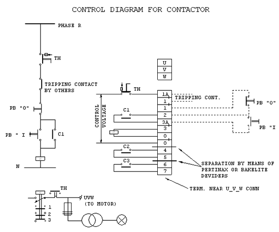
4.12.6 All contactors shall be provided with auxiliary contacts and terminals as indicated in wiring diagram on sheet 30 of this specification.
4.12.7 It must be possible to operate contactors with a control cable of 250 m length ( cable 2.5 mm2 ).
If it is impossible to close contactor due to high inrush current of contactor-coil, vendor shall supply auxiliary relays for this purpose ( see also wiring diagram ).
4.12.8 “Start-stop” rotary switch stations for all motors shall be arranged so that momentary operation of the stop switch stops the motor. Relay will not be acceptable to hold the switch in the stop position for the time of undervoltage.
4.13 Terminals
4.13.1 Terminals shall be grouped with regard to their different voltages.
There shall be a minimum of 5 cm space or separation of insulating material between terminal blocks carrying different voltages.
Separator shall extend one cm above the terminal.
4.13.2 Terminals for outgoing current transformer wiring shall be provided with short-circuit devices.
If open, the link shall point downwards.
5. Tests
5.1 Tests to Be Carried Out in the Factory
( See also Specification for the Inspection of Low Tension Switchgears )
5.1.1 Checking of all control wiring.
5.1.2 Operating test of all protective relays.
5.1.3 Mechanical test ( door locks etc. ).
5.1.4 Appearance test ( painting, near surface, nameplates, etc.).
5.1.5 Megger test. Resistance between busbars and between busbars and ground must be at least 10 megohm.
5.1.6 High potential test 2500 V - 1 minute, unless otherwise specified.
5.1.7 Try to make a short while pulling fuses.
5.1.8 Check accessibility of busbar connection bolts and nuts with normal tools.
5.1.9 Testing of thermal relays with time clock and current injection set to check if relays stay within their curves.
5.2 Test and Proof Operation to Be Carried Out at Site
5.2.1 Megger testing resistance between busbars and between busbars and earth must be at least 10 megohm.
5.2.2 High potential test, 2000 V, 1 minute.
5.2.3 Check of all bolted bus, busduct and transformer connections.
5.2.4 Check of all terminals.
5.2.5 Proof operation and test after announcement “power available”.
5.2.6 Visual inspection for freedom of dust and waste material.
5.3 General Test Procedure
5.3.1 All test equipment necessary for tests described under 5.1 ( and 5.2 if specified ) shall be furnished by vendor.
5.3.2 All tests shall be witnessed by a representative of Company.
6. Metering Equipment and Current Transformers
6.1 Meters
-
Meter shall be flush-mounted in the front of the switchboard. Their minimum size shall be 96 mm2.
-
Remote meters shall not be connected to current transformers provided for to protective relaying.
6.2 Current Transformers
6.2.1 Current transformers shall have accuracy class 1 for metering and accuracy class for protection.
6.2.2 The current transformers shall maintain sufficient accuracy under all overload and short-circuit conditions, to ensure the proper relay operations for protection and selectivity.
6.2.3 Current transformers shall be capable of withstanding the peak momentary short circuit, and the symmetrical short-circuit current for 1 second, unless otherwise specified in the requisition.
7. Unit Type Switchboard
If vendor’s standard unit type switchboards can be adapted to meet the requirements of this specification this type will also be acceptable.
8. Spare Parts
The following spare parts shall be supplied together with the switchgear:
8.1 - 12 fuses of every type used in the switchgear, up to 63 A.
- 6 fuses of every type used in the switchgear, 63 A and above.
8.2 - 10 signal lamps of the same type used in the switchgear.