Table of Contents
- Use of Exchangers
- Types of Exchangers
- Types of Shell and Tube Exchangers
- Layout of Shell and Tube Exchangers in Banks
- Alterations That Can Be Made to Shell and Tube Exchangers
- Establishing Elevations of Exchangers
- Piping
- Layout of Exchangers Other Than in Banks
- Types of Air Fins
- Layout of Air Fins
- Piping
- Fin Tube Exchangers
- Chillers
1. Use of Exchangers
Heat exchangers transfer heat from one media to another. In the petrochemical industry, they can be generally classified under the following headings :
Exchanger: Heats one stream and cools the other. There is no heat loss and physical change in either flowing media.
Cooler: Cools liquid or gases without condensation; applies also to intercooler and aftercooler.
Condenser: Condenses vapour or vapour mixture. Can be water - cooled or by sufficiently cold process stream which requires heating.
Chiller: Uses refrigerant for cooling process stream below freezing point or bellow prevailing cooling water temperature.
Heater (non fired) Heats process stream generally up to its boiling point without appreciable vaporization. Heating medium is usually steam; applies also to preheaters.
Reboiler: Reboils the bottom stream of tower for the fractionation process. Heating medium can be steam or hot process stream. When large quantities of vapor have to be produced the kettle type reboiler is used.
Waste heat boiler: Uses waste heat, such as internal combustion exhaust from gas turbines or similar drivers for steam generation.
Steam generator: Uses heat of process liquid or gas for producing steam.
Vapourizer: Vapourizes part of a process liquid stream as does an evaporator.
2. Types of Exchangers
Briefly, exchangers, etc. , can be divided into the following three groups :
Shell and tube: Which can be vertical or horizontal with the horizontal ones single or stacked in multi-units. As the name suggests, they consist of a cylindrical shell with a nest of tubes inside.
Fin tube:This consist of a finned tube through which passes one media jacketed by another tube through which passes the other media. They can be used as single or multi - units.
Air fins: Come in two shapes ; flat box units and “a” frame units. Both consist of banks of finned tubes through which passes the media to be cooled. Large fans blow air from atmosphere through the banks, thus cooling the flowing media. There are other types, such as plate exchangers, carbon block exchanger, etc., but these are used infrequently.
3. Types of Shell and Tube Exchangers
Floating head exchangers are used when the media being handled causes fairly rapid fouling, and the temperature creates expansion problems. Tubes can expand freely ; channel head and shell cover arrangement is convenient for inspection, and the tube bundle can easily be removed for cleaning.
U-tube exchangers are used when fouling of the tubes on the inside is unlikely. The tubes are free to expand and the bundle can be removed from the shell for cleaning on the shell side of tubes.
Fixed head exchangers have no provision for the tube expansion and unless a shell expansion joint is provided can only be used for relatively low temperature service.
The end covers are removable so that the inside of the tubes can be cleaned by rodding or other similar tools. This type of cleaning is usually carried out in situ so some space should be allowed in the piping layout to allow for this.
4. Layout of Shell and Tube Exchangers in Banks
For good maintenance and safe working conditions, it is necessary to space exchangers such that surrounding area is adequate and clear. They may be spaced apart and grouped in pairs. When apart, a clear access way of 750 mm is considered adequate, this being the clear space between the shells and/or the associated pipework and insulation. For paired exchangers a similar condition is required between pairs and adjacent singles, but between each shell of the pair this may be reduced to 450 mm between head flanges. Exchangers should always be arranged such that the ideally there is a minimum of 150 mm clear at the rear for removal of the bonnet and space provided for dropping it clear of the working area. At the front or channel end, a minimum distance of the tube length plus 2500 mm is considered good. This latter does not of course apply to exchangers located in structures were a total of 1500 mm would be sufficient.
Piping connected to heat exchangers is generally simple. Piping economy and good engineering design depend largely on knowing what alterations can be made to exchangers. In other words, the piping designer can influence the exchanger design. For example, the direction of flow, nozzle locations, etc. Alterations to exchangers of course, should not affect their duty and cost.
Money saved on simpler piping should not be spent on costly alterations to exchangers. The accompanying chart shows the possible alterations that may be instigated by the piping designers to typical shell and tube exchangers without affecting the thermal design. When contemplating such a change it should be remembered that generally the heated media should flow upward, and the cooled media flow downward. This is particularly important if there is a physical change taking place within the exchanger, such as vaporization or condensation. Typical example of this are:
Reboilers where the process stream enters the shell at the bottoms as a liquid and leaves at the top as a vapour after flowing through the tubes, and stream enters the shell near the top of the tubes and leaves at the bottom on the shell as condensate.
Condensers where the process stream enters the shell at the top as a vapour and leaves the bottom as a liquid, whilst cooling water enters the tubes side at the bottom and leaves at the top.
5. Alterations That Can Be Made to Shell and Tube Exchangers
Interchange, flowing media between the tube and shell side. This change is often possible, more so when the flowing media are similar, for example, liquid hydrocarbons. Preferably the hotter media should flow in the tube side to avoid heat losses through the shell, or the necessity for thicker insulation.
Change direction on flow on either tube or shell side. On most exchangers in petrochemical plants, these changes are frequently possible without affecting the required duty of the exchanger if the tubes are in double or multi - pass arrangement and the shell has cross flow arrangement.
In exchangers where counterflow conditions can be arranged, changing of flow direction should be made simultaneously in tube and shell. Some points to consider when contemplating a flow change are :
Shell leakage : When water cooling gases, liquid hydrocarbons or other streams of dangerous nature it is better to have the water in the shell and the process in the tubes, since any leakage of gas, etc. , will contaminate the water rather than leaking to atmosphere.
High pressure conditions : It is usually more economical to have high pressure in the tubes than in the shell as this allows for minimum wall thickness shell.
Corrosion : Corrosive fluids should pass through the tubes, thus allowing the use of carbon steel for the shell.
Fouling : It is preferable to pass the clean stream through the shell and the dirty through the tubes. This allows for easier cleaning. Mechanical changes, such as tangential or elbowed nozzles can sometimes assists in simplifying the piping or lowering stacked exchangers.
6. Establishing Elevations of Exchangers
Where process requirements dictate the elevation, it will usually be noted on the P and I diagram.
From the economic point of view, grade is the best location, where it is also more convenient for the tube bundle handling and general maintenance. Exchangers are located in structures when gravity flow is required to the collecting drum, or where the outlet is connected to a pump suction which has specific NPSH requirements. To elevate exchangers without specific requirements, the following procedure is recommended :
Select the exchanger with the largest bottom connection; add to the nozzle standout dimension ( center line of exchanger to face of flange ) the dimension thru hub of flange, elbow (1 1/2 dia ), one - half the O/S pipe diameter and 300 mm for clearance above grade.
Now subtract the center line to under-side of support dimension from above, and the dimension remaining is the finished height of the foundation including grout.
It is preferable if this foundation height can be made common for all the exchangers in the bank. If this is impracticable due to extremes of shell and/or connection pipe sizes, then perhaps two heights can be decided upon.
When stacking exchangers, two or three high, it is desirable that overall height does not exceed 12’ 0” (3650 mm ) due to the problem of maintenance, bundle pulling, etc.
7. Piping
Plan-wise the exchanger bank should be laid out spaced as noted previously, and all the channel nozzles on a common center line.
This is particularly important if the cooling water headers are underground, as the CW inlets can rise into the lower channel nozzles.
The end of the exchanger adjacent to the rack will normally be the fixed end, if the CW headers are underground the fixed end will become the channel end.
All changes proposed must be discussed fully with Process Engineer and Client Engineer or Vessel Department.
Lines turning right in the yard should be right from the exchanger center line and those turning left should approach the yard on the left-hand side of exchanger center line. Lines from bottom connections should also turn up on the right or the left side of exchangers depending upon which way the line turns in the yard. Lines with valves should turn towards the access aisle with valves and control valves arranged close to exchanger. Utility lines connecting to a header in the yard can be arranged on any side of exchanger center line without increasing pipe length.
Access to valve handwheels and instruments will influence piping arrangement around heat exchangers. Valve handwheels should be accessible from grade and from a convenient access way. These access ways should be utilized for arranging manifolds, control valves and instruments.
In the piping arrangement, provision for tube removal access should be provided. This means a spool piece of flanged elbow in the pipe line connecting to the channel nozzle.
The requirements of good piping layout generally apply to the design of heat exchanger piping. The shortest lines and least number of fittings - temperature permitting - will obviously provide the most economical piping arrangement. The designer should avoid loops, pockets and crossovers, and he should investigate, nozzle to nozzle, the whole length of piping routed from the exchanger to some other equipment, aiming to provide not more than one high point and one low point, no matter how long the line.
Very often a flat turn in the yard, an alternative position for control valves or manifold, changed nozzle location on the exchanger, etc. , can accomplish this requirement.
Avoid excessive piping strains on exchanger nozzles from actual weight of pipe and fittings and from forces of thermal expansion.
For valves and blindes the best location is directly at the exchanger nozzle. In the case of an elbow nozzle on an exchanger it should be checked that sufficient clearances are provided between valve handwheel and outside of exchanger. Elevated valves may require a chain operation. The chain should hang freely at accessible spot near the exchanger.
Below figure shows sketches highlighting exchanger piping details. Orifice flanges in exchanger piping are usually in horizontal pipe runs. These lines should be just above headroom, and the orifice itself accessible with mobile ladder. Orifices in a liquid line and mercury type measuring element require more height. At gas lines the U-tube can be above the line with orifice, consequently the height is not critical. Lines with orifice flanges should have the necessary straight runs before and after the orifice flanges required in specification or standards.
Locally mounted pressure - and temperature indicators on exchanger nozzles, on the shell or process lines, should be visible from the access aisles. Similarly gauge glasses and level controllers on exchangers should be visible and associated valves accessible from this aisles. When arranging instrument connections on exchangers sufficient clearances should be left between flanges and exchanger support between instruments and adjacent piping. Insulation of piping and exchangers should also be taken into account.
8. Layout of Exchangers Other Than in Banks
Process equipment in most plants is arranged in the sequence of process flow. However, whatever layout system is used, the general evaluation regarding exchanger positions is very similar.
In layout the fractionation towers should be located in proper sequence first, although often the arrangement of other equipment - for example, condensers depend directly upon the tower orientation, and sometimes the decision whether to use a structure or not depends upon this. This relative position of exchangers can be readily evaluated from flow diagrams. For exchanger positions in a petrochemical plant the following general classification can be made.
Exchangers which must be next to other equipment. Such exchangers are the reboilers which should be located to their respective towers, or condensers which should be next to their reflux drums close to the tower.
Exchangers which should be close to other process equipment. For example, exchangers in closed pump circuits such as some reflux circuits. Overhead condensers should also be close to their tower to ensure that the line pressure drop in minimal. In case of tower-bottom-draw-off-exchanger-pump flow, exchangers should be close to the tower or drum, to give short suction lines.
Exchangers located between distant items of process equipment. These are for example, exchangers with process lines connected to both shell and tube side. Where parallel run is the ideal location for this type of exchanger. On that side of the yard, where the majority of related equipment is placed. Other locations will cost more in pipe runs.
Exchangers located between process equipment and the unit limit. Such exchangers are for example product coolers. These are frequently located near the unit limit.
Stacked exchangers. A further step in the layout is to establish which exchangers can be stacked for simplifying piping and saving plot space. Most units in the same service are grouped automatically. Two exchangers in series or parallel are usually stacked. Sometimes, small diameter exchangers in series can be stacked three high. Two exchangers in dissimilar services can also be stacked. Sufficient clearance must be provided for shell and channel side piping between the two exchangers. Reboilers and single condensers usually stand by themselves beside their respective towers. Vertical thermosyphon reboilers are usually hung from the side of their associated tower.
9. Types of Air Fins
There are two types of air fin construction : the box type and the “A” frame type.
The box type can be divided into two forms : forced draught and induced draught.
Forced draft air fins are the most commonly used type, possibly because maintenance of the fan is easy from an underslung platform.
“A” frame type air fins less common than the box type.
They offer the advantage of requiring less plot area than box type air fins of the same capacity. They do, however, present a few problems. Due to physical shape of them, i.e. triangular section with the apex uppermost, the inlet header is located at the apex, with the collecting headers at both bottom corners. This means that cooled product lines are coming off both sides of the rack which can present piping problems. Also, with 60o sides containing the product, it is possible to get uneven cooling due to the sun being on one side, or the prevailing wind tending to blow into the tube bank against the fan.
10. Layout of Air Fins
Air fins are large compared with shell and tube exchangers, and it is not uncommon for them to occupy several thousand square feet of plot area on a unit.
If this plot area is required at grade, there could well be siting problems, but fortunately most process using air fins require a gravity feed through them, which means they must be elevated.
The most common satisfactory location is on top of the main pipe rack. Pipe rack width is invariably determined by tube length of air fin units. In the absence of sufficient room on the rack, they may be located on top of any suitable structure, or an elevated structure may be built for the purpose.
When locating air fins on the plot a number of points have to be borne in mind.
Air fin of a given capacity could be made up of several units each weighing several tons.
It is important that each unit be reached by the site crane for erection and maintenance purposes. Therefore, the overall plot layout must provide for this crane access.
As most air fins will be condensing overheads from towers, it is important to consider the explanation problems of the overhead line when siting the relevant air fin, as air fins are unsuitable for accepting high loads on the nozzles.
Access platforms are always provided either side of the air fin for access to the header boxes, and underneath the units for access to fans and motors. Provision must be made for grade to all these platforms at least at either end.
It is a good idea to investigate connecting these access ways to adjacent structures to provide intermediate escape and for operational convenience.
11. Piping
There are four major problems when piping-up airfins :
- Correct configurations of piping to give equal or as near equal distribution as possible of the product through each unit of multi-unit air fins.
- Make piping from tower overhead as short as possible to minimize pressure drop.
- Obtaining a piping system that is sufficiently flexible to avoid overloading the unit nozzles.
- Providing sufficiently suitable pipe supports and anchors.
Below figure shows diagrammatically three methods of piping for distribution :
- Showing good distribution
- Showing good distribution
- Showing bad distribution
When designing the piping for air fin exchangers, the basic rules of piping still apply, that the piping runs should be as short and direct as possible, but at the same time be sufficiently flexible to avoid overloading the air fin nozzles. The below figure shows two methods of running product headers to air fins :
By running the inlet header down the center of the units, the off-takes to the unit drop out of the bottom of the header, run across the units and drop into the nozzles.
Thus, we have a series of off-takes sufficiently long to absorb expansion, at the same time having the minimum of elbows resulting in minimum pressure drop.
Supports can usually be attached to the steel members that run between units and are thus short and minimal. The header must be flanged at intervals along its length to facilitate the removal of units by crane for maintenance.
The preferred position for the header is directly above the inlet nozzles, keeping the branches as short as possible. Make sure that the air fin is capable of excepting the movement imposed on the header. Support from the rack steel is between the header boxes.
Outlet headers are less of a problem because the temperature is lower and the pipe size usually much smaller.
They can usually be supported off the air fin legs beneath the header box platform.
Any valves required to isolate units are the best located on the unit nozzles. Sometimes air fins handling light hydrocarbons may require snuffing steam supply.
These should be treated in the same way as snuffing steam to heaters, insomuch as the valves should be located at least 15 meters radius planwise from the perimeter of the air fin.
Piping runs that place loads of any sort on the air fin structures should be avoided if possible, or communicated to the vendor as soon as possible.
12. Fin Tube Exchangers
Fin tube exchangers consist of a hairpin shaped inner tube with heat transfer fins on the outside, except for the return bend.
The two legs are jacketed with larger bore pipe.
The heat exchange is achieved by the stream passing through the hairpin, and the other passing through the jackets. They may be used singly or in multiples.
The primary uses are for heathers or coolers; that is, the process stream passes through the inner tube and either steam or cooling water passes through the jackets. They are used mainly as a source of local heat exchange, such as outlet heaters from the tanks and drums to pumps, etc.
Our important point to remember when locating fin tubes is that the hairpin tube draws out from the back end, that is, the opposite end from the nozzles, and sufficient room must be allowed for this purpose.
Piping design considerations are similar to those on shell and tube exchangers.
13. Chillers
Chillers are used where the process stream requires cooling to lower temperature than possible with cooling water, and for this purpose it is necessary to use a refrigerant.
Depending upon the size of the chillers installation, the refrigerant can either be supplied by a proprietary package unit, or a custom-built job using LPG. The construction is similar to fin tube, insomuch as the tube within a tube feature is common.
Chillers usually consist of a multi-unit bank with the process stream passing through the inner tube and the refrigerant passing through the jackets. Once again space must be allowed at the rear for tube withdrawal. An important thing to remember when laying out these exchangers, is the considerable thickness of insulation required on all the pipe-work, necessitating larger than normal pipe spacing.
Figures
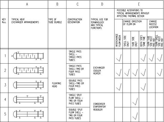
TYPICAL EXCHANGERS - SHOWS POSSIBLE ALTERATIONS FOR BETTER PIPING
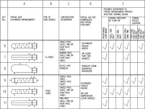
TYPICAL EXCHANGERS - SHOWS POSSIBLE ALTERATIONS FOR BETTER PIPING
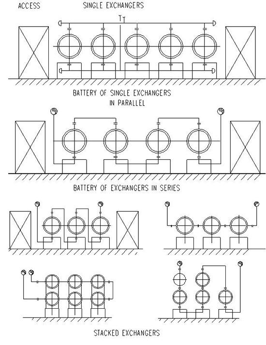
TYPICAL EXCHANGER GROUPINGS
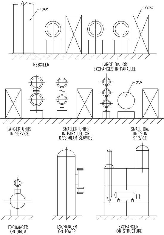
TYPICAL EXCHANGER GROUPINGS
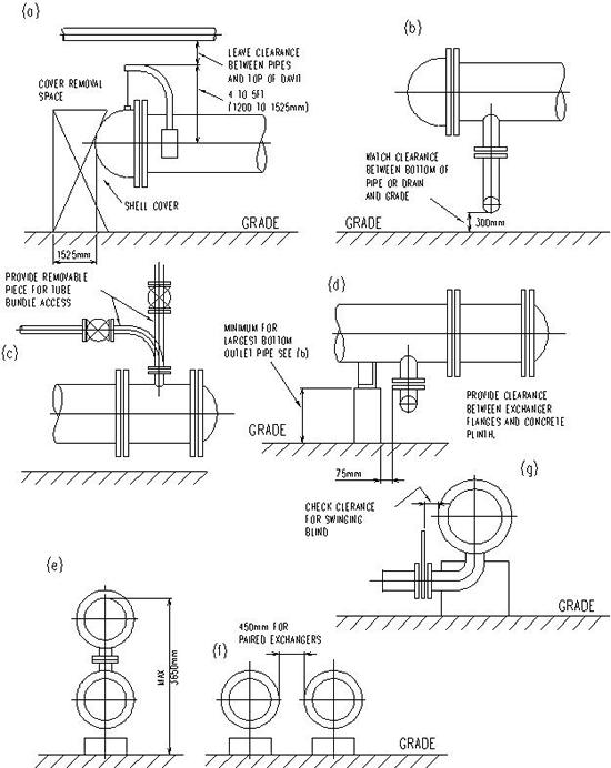
MINIMUM CLEARANCES FOR HEAT EXCHANGERS
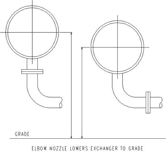
NOZZLE ARRANGEMENT FOR BETTER PIPING
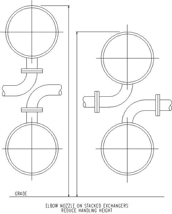
NOZZLE ARRANGEMENT FOR BETTER PIPING
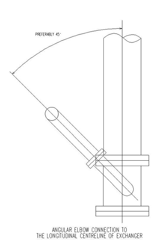
NOZZLE ARRANGEMENT FOR BETTER PIPING

NOZZLE ARRANGEMENT FOR BETTER PIPING
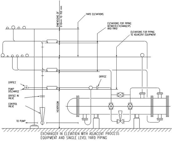
EXCHANGER PIPING ARRANGEMENT
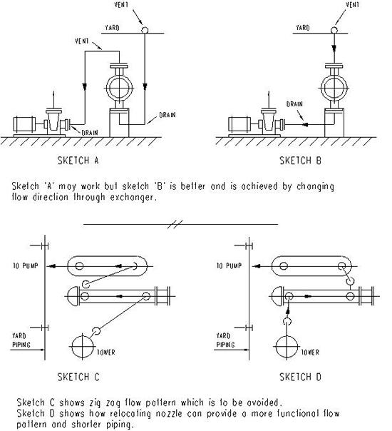
BETTER PIPING ARRANGEMENTS
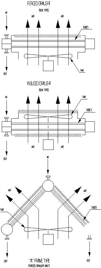
TYPES OF AIR FIN EXCHANGERS
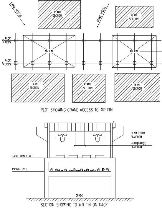
PLOT ACCESS & SECTION OF AIR FIN
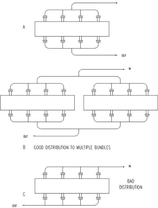
AIRFIN MANIFOLD LAYOUT
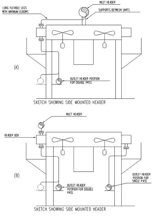
HEADER MOUNTINGS FOR AIR FIN

