Input variables
Generic variables
These variables can be found in virtually all reports as input variables
- Design Pressure – Pd
- Pressure assumed to be present in the component according to the design terms
- Design Temperature – Td
- Temperature assumed to be present in the component according to the design terms
- Material
- Name of selected material used for the construction of the component
Specific variables
These variables are component specific
- Outside Diameter – De
- Outside diameter of the attached part. The diameter runs from the outside of the wall to the opposite outside of the wall, through the center of the circle.
- Nominal Thickness – dn
- Thickness ‘as is’, meaning it is the design thickness taking into account corrosion and tolerance.
- Corrosion – Ca
- Amount of thickness that accounts for the possible effects of corrosions.
- Tolerance – tol
- Tolerance in thickness for production
- Strength reduction coefficient – z
- Effectiveness of the strength, depending on whether joints are seamless, welded, or expected to perform worse than the base material properties
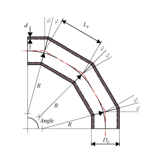
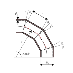
- Radius miter bend – R
- Radius of the miter bend from the origin of curvature and perpendicular to the neutral axis of the bend. The neutral axis follows the centerlines of the segments.
- Total deflection angle miter bend – Angle
- The angle of the total deflection the miter bend makes, i.e. the angle between the centerlines of the attached pipes.
- Number of Segments – NoS
- The number of segments in which the bend is divided.
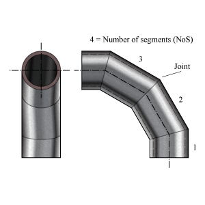
Miter Bend
Miter Bend Widely Spaced
Miter Bend Closely Spaced
Calculated Values
- Allowable Stress at Temperature – f
- Stress in the component at which it is still allowed (without failure) to use the component
- Allowable stress at 20 °C – ft
- Stress in the component at which it is still allowed (without failure) to use the component at 20 °C ambient temperature
- Miter bend cut angle – φ
- Cutting angle between the different segments.
- Segment length at centerline – Ls
- Length of the segment measured at the centerline.
- Minimum segment length at centerline – Ls min
- Minimum required segment length measured at the centerline.
- Nominal Required Thickness – drn
- Based on the input, this is the calculated thickness that is required to sustain the loads. The nominal value should be smaller than the nominal design thickness.
- Ratio outside diameter to thickness – De / d
- Ratio for the relationship with Pd / f and φ in figure 2.
- Maximum Allowable Working Pressure – MAWP
- The maximum pressure at which the component can be used in operation. This value should be larger than the design pressure.
- Design margin – Pd / MAWP
- Ratio of the design pressure to MAWP
- Maximum Allowable Test Pressure – MATP
- The maximum pressure at which the component should be tested and survive.
Scope errors
- Design temperature material is out of scope.
- The material properties are not available at the design temperature.
- Number of segments is out of scope: required is NoS ≥ 2
- A miterbend has at least 2 segments.
- Angle of miter cut is out of scope: required is φ ≤ 22.5°
- This code determines a maximum angle.
- Segment length is out of scope: required is Ls ≥ Lsmin
- This code determines a minimum length.
- Miter bend is not allowed in creep range.
- This code determines that miter bends are not applicable in the creep range.
- Ratio of diameter to thickness is out of scope: required 20 ≤ De/d ≤ 200 (fig. 2).
- Fig.2 shows a relationship between d /De versus Pd /f
Errors
- Can’t find material ‘MaterialName’ in database
- Material could not be found in database. Select an existing material name, or select another material via the material selection window.
- Insufficient wall thickness
- Wall thickness is insufficient to bear the applied loads. Increase the wall thickness.
Calculation errors
- Can't calculate required thickness. Please check input data.
- An error occured in the calculation for the required thickness.