Input variables
Generic variables
These variables can be found in virtually all reports as input variables
- Design Pressure – Pd
- Pressure assumed to be present in the component according to the design terms
- Design Temperature – Td
- Temperature assumed to be present in the component according to the design terms
- Material cylinder, cone
- Name of selected material used for the construction of the component
Specific variables
These variables are component specific
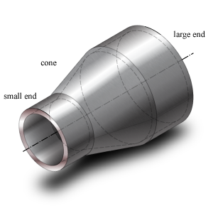
- Large/Small
- Large and Small refer to the large pipe end and the smaller (reduced) pipe end respectively
- Outside Diameter cylinder, cone – De
- Outside diameter of the attached part. The diameter runs from the outside of the wall to the opposite outside of the wall, through the center of the circle.
- Nominal Thickness cylinder, cone – dcn, dkn (Large/Small)
- Thickness ‘as is’, meaning it is the design thickness taking into account corrosion and tolerance.
- Corrosion – Ca
- Amount of thickness that accounts for the possible effects of corrosions.
- Tolerance – tol
- Tolerance in thickness for production
- Length conical part – Lk
- Length of the part that reduces gradually in diameter and hence, forms a conical shape
- Angle cone – α
- The angle of the conical section, or the slope with which the diameter reduces.
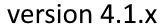
Concentric reducer
Concentric reducer dimensions
Eccentric reducer
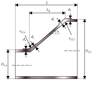
Eccentric reducer dimensions
Calculated Values
- Yield strength at operating temperature – Re (Large/Small)
- Stress in the component at which the component starts to plastically deform at operating temperature.
- Modulus of elasticity – E (Large/Small)
- Tendency to deform (tensile strain) along an axis when opposing forces (tensile stress) are applied along that axis.
- Poisson's ratio ν
- (Negative) ratio of transverse to axial strain. An extension (or contraction) in the direction of a load corresponds in a contraction (or extension) in a direction perpendicular to the applied load. The ratio between these two quantities is the Poisson's ratio.
- Axial stresses cylinder – Sax:c (Large/Small)
- Stress that tends to stretch the component along the axial direction.
- Axial stresses cone – Sax:k (Large/Small)
- Stress that tends to stretch the component along the axial direction.
- Tangential stresses cylinder – Stg:c (Large/Small)
- Stress that tends to stretch the component along the tangential (circumferential) direction. Also called hoop stress.
- Tangential stresses cone – Stg:k (Large/Small)
- Stress that tends to stretch the component along the tangential (circumferential) direction. Also called hoop stress.
- Combined stresses cylinder – Sv:c (Large/Small)
- Stress that results from several stresses acting in several directions.
- Combined stresses cone – Sv:k (Large/Small)
- Stress that results from several stresses acting in several directions.
- Required effective junction length cylinder, cone – lc, lk (Large/Small)
- Minimum axial length along the cylinder or cone in the junction to sustain the loads.
- Maximum Allowable Working Pressure – MAWP (Large/Small)
- The maximum pressure at which the component can be used in operation. This value should be larger than the design pressure.
- Design margin – Pd / MAWP
- Ratio of the design pressure to MAWP
- Maximum Allowable Test Pressure – MATP (Large/Small)
- The maximum pressure at which the component should be tested and survive.
Scope errors
- Design temperature material is out of scope.
- The material properties are not available at the design temperature.
- Cone angle is out of scope: required α ≤ 70° (paragraph 1).
- This code determines a maximum cone angle.
Errors
- Can’t find material ‘MaterialName’ in database
- Material could not be found in database. Select an existing material name, or select another material via the material selection window.
- Combined stress at large end concentric or eccentric cylinder junction Sv:c is too large (paragraph 3).
- The combined stress exceeds the allowable stress.
- Combined stress at large end concentric or eccentric cylinder junction Sv:c:i is too large (paragraph 3).
- The combined stress at the inside exceeds the allowable stress.
- Combined stress at large end concentric or eccentric cylinder junction Sv:c:e is too large (paragraph 3).
- The combined stress at the outside exceeds the allowable stress.
- Combined stress at large end concentric or eccentric cone junction Sv:k is too large (paragraph 3).
- The combined stress exceeds the allowable stress.
- Combined stress at large end concentric or eccentric cone junction Sv:k:i is too large (paragraph 3).
- The combined stress at the inside exceeds the allowable stress.
- Combined stress at large end concentric or eccentric cone junction Sv:k:e is too large (paragraph 3).
- The combined stress at the outside exceeds the allowable stress.
- Combined stress at small end concentric or eccentric cylinder junction Sv:c is too large (paragraph 3).
- The combined stress exceeds the allowable stress.
- Combined stress at small end concentric or eccentric cylinder junction Sv:c:i is too large (paragraph 3).
- The combined stress at the inside exceeds the allowable stress.
- Combined stress at small end concentric or eccentric cylinder junction Sv:c:e is too large (paragraph 3).
- The combined stress at the outside exceeds the allowable stress.
- Combined stress at small end concentric or eccentric cone junction Sv:k is too large (paragraph 3).
- The combined stress exceeds the allowable stress.
- Combined stress at small end concentric or eccentric cone junction Sv:k:i is too large (paragraph 3).
- The combined stress at the inside exceeds the allowable stress.
- Combined stress at small end concentric or eccentric cone junction Sv:k:e is too large (paragraph 3).
- The combined stress at the outside exceeds the allowable stress.