Input variables
Generic variables
These variables can be found in mostly all reports as input variables
- Gas infrastructure
- Location of the facility near which the gas infrastructure is situated.
- Underground, except a station
- In a tunnel
- Station
- Maximum Design Factor – fo
- Factor for restricting the allowable stress. The value can be chosen smaller, but not larger.
- Design Pressure – DP
- Pressure assumed to be present in the component according to the design terms
- Design Temperature – θ
- Temperature assumed to be present in the component according to the design terms
- Material
- Name of selected material used for the construction of the component
Specific variables
These variables are component specific
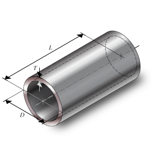
- Outside Diameter – D
- Outside diameter of the attached part. The diameter runs from the outside of the wall to the opposite outside of the wall, through the center of the circle.
- Nominal Thickness – Tn
- Thickness ‘as is’, meaning it is the design thickness taking into account corrosion and tolerance.
- Corrosion – Ca
- Amount of thickness that accounts for the possible effects of corrosions.
- Tolerance – tol
- Tolerance in thickness for production
- Strength reduction coefficient – z
- Effectiveness of the strength, depending on whether joints are seamless, welded, or expected to perform worse than the base material properties
- Length tangent to tangent – L
- Length of the straight part of the pipe (equals the unsupported length of the pipe)
Pipe
Calculated Values
- Yield strength at operating temperature – Rt
- Stress in the component at which the component starts to plastically deform at operating temperature.
- Minimum yield strength at 20 °C – Rta
- Stress in the component at which the component starts to plastically deform at 20 °C ambient temperature
- Allowable Stress at Temperature – S
- Stress in the component at which it is still allowed (without failure) to use the component
- Allowable stress at 20 °C – St
- Stress in the component at which it is still allowed (without failure) to use the component at testing condition
- Nominal Required Thickness – Trn
- Based on the input, this is the calculated thickness that is required to sustain the loads. The nominal value should be smaller than the nominal design thickness.
- Maximum Allowable Working Pressure – MAWP
- The maximum pressure at which the component can be used in operation. This value should be larger than the design pressure.
- Design margin – DP/MAWP
- Ratio of the design pressure to MAWP
- Maximum Allowable Test Pressure – MATP
- The maximum pressure at which the component should be tested and survive.
Scope errors
- Design pressure is out of scope: minimum operating pressure > 16 bar.
- This code determines a minimum pressure.
- Design temperature is out of scope: required -40 °C ≤ T ≤ 120 °C.
- This code determines a minimum and maximum temperature.
- Design factor is too large: required is fo ≤ fomax (see 7.2).
- This code determines a maximum design factor.
- Wall thickness is out of scope according paragraph 7.9.2 Table 1.
- This code determines for pipes a minimum thickness.
Errors
- Can’t find material ‘MaterialName’ in database
- Material could not be found in database. Select an existing material name, or select another material via the material selection window.
- Insufficient wall thickness
- Wall thickness is insufficient to bear the applied loads. Increase the wall thickness.