Input variables
Generic variables
These variables can be found in virtually all reports as input variables
- Design Pressure – Pc
- Pressure assumed to be present in the component according to the design terms
- Design Temperature – T
- Temperature assumed to be present in the component according to the design terms
- Material (header/branch)
- Name of selected material used for the construction of the component
Specific variables
These variables are component specific.
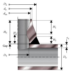
- Outside Diameter branch and header – do, Do
- Outside diameter of the attached part. The diameter runs from the outside of the wall to the opposite outside of the wall, through the center of the circle.
- Inside Diameter – din
- Inside diameter at the top.
- Shoulder Diameter – D2
- Largest outside diameter.
- Diameter hole in header – D3
- Internal diameter opening between header and branch. Equal to the inside diameter at the bottom.
- Overall height branch – H0
- Height from top to bottom.
- Height at shoulder to branch – H1
- Height from the top to the largest outside diameter
- Height at inside beveled area – H2
- Height from the bottom to the smallest inside diameter.
- Height at welding area header – H3
- Available height at bottom for welding
- Gap between header and weldolet – Gap
- Clearance distance at bottom for welding
- Nominal Thickness Header – esn
- Thickness ‘as is’, meaning it is the design thickness taking into account corrosion and tolerance.
- Corrosion – c0, c0s
- Amount of thickness that accounts for the possible effects of corrosion.
- Tolerance header –c1s
- Tolerance in thickness for production
- Joint coefficient header – zs
- Effectiveness of the strength, depending on whether joints are seamless, welded, or expected to perform worse than the base material properties.
Weldolet dimensions
Calculated Values
- Allowable Operating Stress – f, fs
- Stress in the branch and the header at which it is still allowed (without failure) to use the component.
- Allowable stress at 20 °C – ft, fst
- Stress in the branch and the header at which it is still allowed (without failure) to use the component at testing condition.
- Stress ratio – f/fs, ft/fst
- Ratio of the allowable stresses in the branch and the header
- Reinforcement limit header direction – ls
- Length from the branch outside diameter to the end of the header reinforcement zone.
- Reinforcement limit branch direction – lb
- Length from the header outside diameter to the end of the branch reinforcement zone.
- Material area header – Afs
- Cross-sectional area of header material between reinforcement limits.
- Material area branch – Afb
- Cross-sectional area of branch material between reinforcement limits.
- Pressure area header – Aps
- Cross-sectional area with pressure in header between reinforcement limits.
- Pressure area branch – Apb
- Cross-sectional area with pressure in branch between reinforcement limits.
- Total pressure area – Ap
- Total cross-sectional area with pressure in header and branch between reinforcement limits.
- Pressure force – Fp
- Total force of the design pressure on the total pressure area.
- Maximum allowable pressure force – Fpmax
- Maximum allwable force of the design pressure on the total pressure area.
- Maximum Allowable Working Pressure – MAWP
- The maximum pressure at which the component can be used in operation. This value should be larger than the design pressure.
- Design margin – Pc/MAWP
- Ratio of the design pressure to MAWP
- Maximum Allowable Test Pressure – MATP
- The maximum pressure at which the component should be tested and survive.
Scope errors
- No header pipe dimensions specified.
- A header pipe is needed for the calculations.
Errors
- Can’t find material ‘MaterialName’ in database
- Material could not be found in database. Select an existing material name, or select another material via the material selection window.
- Insufficient wall thickness for header
- Wall thickness is insufficient to bear the applied loads. Increase the wall thickness of the header.
- Insufficient reinforcement area.
- Reinforcement area is too small. Increase the reinforcement area or thickness.