Input variables
Generic variables
These variables can be found in virtually all reports as input variables
- Design Pressure – Pc
- Pressure assumed to be present in the component according to the design terms
- Design Temperature – T
- Temperature assumed to be present in the component according to the design terms
- Material
- Name of selected material used for the construction of the component
Specific variables
These variables are component specific
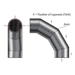
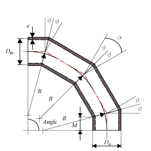
- Outside Diameter – Do
- Outside diameter of the attached part. The diameter runs from the outside of the wall to the opposite outside of the wall, through the center of the circle.
- Nominal Thickness – en
- Thickness ‘as is’, meaning it is the design thickness taking into account corrosion and tolerance.
- Corrosion – c0
- Amount of thickness that accounts for the possible effects of corrosions.
- Tolerance – c1
- Tolerance in thickness for production
- Joint coefficient – z
- Effectiveness of the strength, depending on whether joints are seamless, welded, or expected to perform worse than the base material properties
- Radius miter bend – R
- Radius of the miter bend from the origin of curvature and perpendicular to the neutral axis of the bend. The neutral axis follows the centerlines of the miter joints.
- Total deflection angle miter bend – Angle
- The angle of the total deflection the miter bend makes, i.e. the angle between the centerlines of the attached pipes.
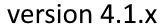
- Number of segments – NoS
- The number of joints in which the bend is divided.
Miter Bend
Multiple Miter Bend Widely Spaced
Multiple Miter Bend Closely Spaced

Single Miter Bend
Calculated Values
- Allowable Stress at Temperature – f
- Stress in the component at which it is still allowed (without failure) to use the component.
- Allowable stress at 20 °C – ft
- Stress in the component at which it is still allowed (without failure) to use the component at testing condition.
- Miter bend cut angle – θ
- Cutting angle between the different joints.
- Change in direction at miter joint – α = 2θ
- The total angle of deflection per miter joint.
- Maximum calculation pressure – Pc max
- Maximum pressure allowed when the stress is time dependent or not.
- Minimum miter bend radius – Rmin
- Minimum required bend radius
- Minimum inside length of sleeve segment ends – M
- Minimum length of the segment measured at the inside.
- Multiple/Single miter bend type
- A miter bend is called a multiple miter bend with 3 or more segments, otherwise a single miter bend with 2 segments.
- Nominal Required Thickness – ern
- Based on the input, this is the calculated thickness that is required to sustain the loads. The nominal value should be smaller than the nominal design thickness.
- Maximum Allowable Working Pressure – MAWP
- The maximum pressure at which the component can be used in operation. This value should be larger than the design pressure.
- Design margin – Pc/MAWP
- Ratio of the design pressure to MAWP
- Maximum Allowable Test Pressure – MATP
- The maximum pressure at which the component should be tested and survive.
Scope errors
- Number of segments is out of scope: required is NoS ≥ 2
- A miterbend has at least 2 segments.
- For time dependent design stress: required Pc ≤ 0.4 MPa
- This code determines for loads that vary in time a maximum pressure.
- For time dependent design stress: required cycles ≤ 100
- This code determines for loads that vary in time a maximum number of cycles.
- For time independent design stress: required Pc ≤ 2 MPa
- This code determines for loads that are constant in time a maximum pressure.
- For time independent design stress and change in direction α > 22.5°: required cycles ≤ 7000
- This code determines for loads that are constant in time a maximum number of cycles.
- No calculation required when deflection angle per miter α ≤ 3°
- This code determines a minimum angle of miter cut θ. Decrease the number of miter segments or increase the total deflection angle of the miterbend.
- For multiple miter bends, the miter cut angle is out of scope: required is θ ≤ 22.5°
- This code determines for multiple miter bend a maximum angle.
- Miter bend radius is out of scope: required is R ≥ Rmin mm.
- This code determines a minimum radius.
Errors
- Can’t find material ‘MaterialName’ in database
- Material could not be found in database. Select an existing material name, or select another material via the material selection window.
- Insufficient wall thickness
- Wall thickness is insufficient to bear the applied loads. Increase the wall thickness.
Remarks
- For single miter bends, the miter cut angle θ is larger than 22.5°.
- The Maximum Allowable Pressure drops rapidly when the angle exceeds this limit.
Calculation errors
- Can't calculate required thickness. Please check input data.
- An error occured in the calculation for the required thickness.