Input variables
Generic variables
These variables can be found in virtually all reports as input variables.
- Design Pressure – P
- Pressure assumed to be present in the component according to the design terms.
- Design Temperature – T
- Temperature assumed to be present in the component according to the design terms.
- Material
- Name of selected material used for the construction of the component.
- Weld fitting option – W
- Is the fitting welded
Specific variables
These variables are component specific.
- Large/Small
- Large and Small refer to the large pipe end and the smaller (reduced) pipe end respectively.
- Outside Diameter – Do (Large/Small)
- Outside diameter of the attached part. The diameter runs from the outside of the wall to the opposite outside of the wall, through the center of the circle.
- Nominal Thickness – tn (Large/Small)
- Thickness ‘as is’, meaning it is the design thickness taking into account corrosion and tolerance.
- Corrosion – A
- Amount of thickness that accounts for the possible effects of corrosions.
- Tolerance – tol (Large/Small)
- Tolerance in thickness for production.
- Joint Efficiency – E
- Effectiveness of the strength, depending on whether joints are seamless, welded, or expected to perform worse than the base material properties.
- Overall length – L
- Length of the entire reducer.
- Length conical part – Lc
- Length of the part that reduces gradually in diameter and hence, forms a conical shape.
- Angle cone – α
- The angle of the conical section, or the slope with which the diameter reduces.
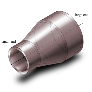
Concentric reducer
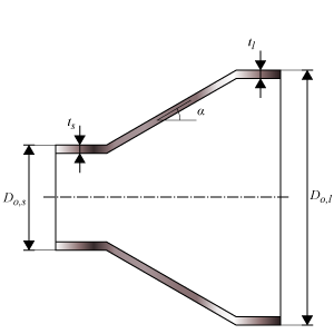
Concentric reducer dimensions
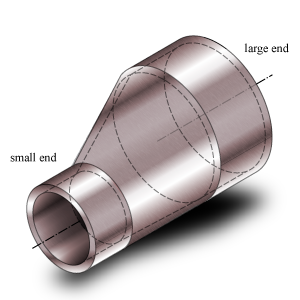
Eccentric reducer
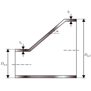
Eccentric reducer dimensions
Calculated Values
- Allowable Operating Stress – S
- Stress in the component at which it is still allowed (without failure) to use the component.
- Allowable stress at 20 °C – Sa
- Stress in the component at which it is still allowed (without failure) to use the component at 20 °C ambient temperature.
- Minimum yield strength at 20 °C – Symin
- Stress in the component at which the component starts to plastically deform at 20 °C ambient temperature.
- Allowable stress test – St
- Stress in the component at which it is still allowed (without failure) to use the component at testing condition.
- Weld joint strength reduction – W
- Factor by which the allowable strength is reduced in order to accommodate the reduction in strength in the welded joint.
- Nominal Required Thickness – trn (Large/Small)
- Based on the input, this is the calculated thickness that is required to sustain the loads. The nominal value should be smaller than the nominal design thickness.
- Maximum Allowable Working Pressure – MAWP (Large/Small)
- The maximum pressure at which the component can be used in operation. This value should be larger than the design pressure.
- Design margin – P/MAWP (Large/Small)
- Ratio of the design pressure to MAWP
- Maximum Allowable Test Pressure – MATP (Large/Small)
- The maximum pressure at which the component should be tested and survive.
- Required Test Pressure – Pt
- Required hydrostatic pressure for testing at any point in the piping system (paragraph 137.4.5)
Scope errors
- Pressure for steam/vapor is out of scope: minimum pressure = 0.1 MPa
- This code determines for steam/vapor a minimum pressure.
- Pressure for water is out of scope: minimum pressure = 1.103 MPa
- This code determines for water a minimum pressure.
- Temperature for water is out of scope: minimum temperature = 100 °C
- This code determines for water a minimum temperature.
- Reducer angle is out of scope: maximum angle = 30°
- This code determines a maximum reducer angle.
Errors
- Can’t find material ‘MaterialName’ in database
- Material could not be found in database. Select an existing material name, or select another material via the material selection window.
- Insufficient wall thickness at large end.
- Wall thickness is insufficient to bear the applied loads. Increase the wall thickness.
- Insufficient wall thickness at small end.
- Wall thickness is insufficient to bear the applied loads. Increase the wall thickness.