Table of Contents
- Purpose
- Responsibilities
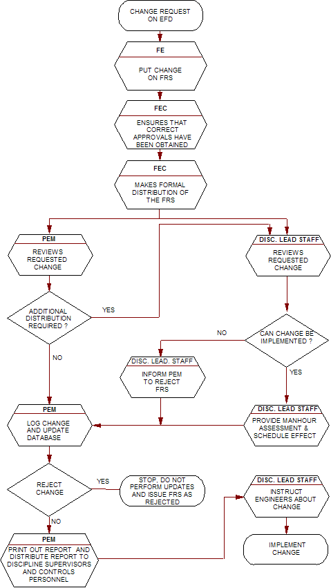
- Work Instruction (see flowchart in section 4)
- Flowchart
- References
- Attachments
1. Purpose
This work instruction defines the method to be utilized for approving, quantifying and tracking of changes to Engineering Flow Diagrams (EFD’s) by means of a Flowsheet Revision Sheet (FRS). These FRS's can be utilized as a tool for the following parameters:
- cost of change per discipline;
- who is responsible for the revision and what was the cause of a change;
- improve awareness of the cost of revisions;
- assessment of performance at the end of the project.
2. Responsibilities
The Flowsheet Engineers (FE) are responsible for initiating the FRS.
The Flowsheet Engineering Co-ordinator (FEC) ensures that the necessary approvals are obtained. He is responsible for issue and shall ensure that the correct distribution is made to inform the personnel affected by the revisions. The Project Engineering Manager shall verify if additional distribution of the FRS is required
The Project Engineering Manager (PEM) or his delegate shall set up and keep up-to-date the database necessary to monitor the revisions and the manhour cost. The Project Engineering Manager or his delegate shall ensure that lead personnel affected by the revisions forward the impact of the revisions on their discipline's manhour budget and schedule.
3.Work Instruction (see flowchart in section 4)
Once the requirement for the change to an EFD has been determined, an FRS shall be completed which shall contain a description of the change and the reason for the change. If appropriate, a sketch should also be included. For example of a FRS see Attachment 1. The FEC shall approve the FRS and shall obtain approval from the Project Manager. The FRS shall then be formally distributed to the personnel affected by the change. Upon receipt of the FRS, the Project Engineering Manager will log the FRS and will obtain input from the groups about the manhours required and any time delays expected from the change. For an example of such a logsheet see Attachment 2.
4.Flowchart

5.References
None.
6.Attachments
- Typical Example FRS (2 sheets)
- Typical Example FRS Log (1 sheet)
| Flowsheet Revision Sheet No.: FRS-C- 129 Sheet 1 of 2 | |||||||||
| Project No.: | Flowsheet No.: 12-3A-BN-C78-00001 | Date: | |||||||
| Sketch: | |||||||||
| See attached detail of P&ID | |||||||||
| Description: Reroute return line of SC-2 to suction of PA24302A/B, add two 1” valves and blind off 2” gatevalve WG24130. This valve will be the connection for a future analyzer. |
|||||||||
| Reason: Client requested this connection. See 00010-NHT-BN-0709, item 2.6 | |||||||||
| These changes have been reviewed for safety and operability and no impact on the HAZOP has been found. | |||||||||
| Initiating Department: | Group | Est. Manhours | |||||||
| Originator:MvV / PHS | Supervisor: | Systems | |||||||
| Piping | |||||||||
| Approved: | Rejected: | Mechanical | |||||||
| (by Proj. Manager) | (by Proj. Manager) | Process | |||||||
| Vessels | |||||||||
| Civil | |||||||||
| Distribution: | Electrical | ||||||||
| Client: | Civil: | Instruments | |||||||
| File: | Struct. | Structural | |||||||
| Process: | Electr: | Project | |||||||
| Piping Des | Constr: | Other Below | |||||||
| Instrum. | HES: | ||||||||
| Project: | Piping Eng: | ||||||||
| Proj.Contr | Underground: | ||||||||
| Mech | Fire Fighting | Total | |||||||
| Additional material or other requirements to implement the change: | |||||||||

Example FRS Log


