Input variables
Generic variables
These variables can be found in virtually all reports as input variables
- Design Pressure – P
- Pressure assumed to be present in the component according to the design terms
- Design Temperature – T
- Temperature assumed to be present in the component according to the design terms
- Material
- Name of selected material used for the construction of the component
- Weld fitting option – W
- Is the fitting welded
Specific variables
These variables are component specific
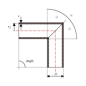
- Outside Diameter – D
- Outside diameter of the attached part. The diameter runs from the outside of the wall to the opposite outside of the wall, through the center of the circle.
- Nominal Thickness – tn
- Thickness ‘as is’, meaning it is the design thickness taking into account corrosion and tolerance.
- Corrosion – c
- Amount of thickness that accounts for the possible effects of corrosions.
- Tolerance – tol
- Tolerance in thickness for production
- Joint Efficiency – E
- Effectiveness of the strength, depending on whether joints are seamless, welded, or expected to perform worse than the base material properties
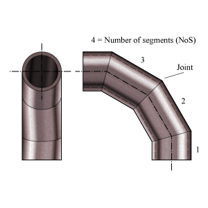
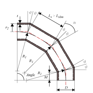
- Radius miter bend – R1
- Radius of the miter bend from the origin of curvature and perpendicular to the neutral axis of the bend. The neutral axis follows the centerlines of the segments.
- Total deflection angle miter bend – Angle
- The angle of the total deflection the miter bend makes, i.e. the angle between the centerlines of the attached pipes.
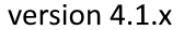
- Number of Segments – NoS
- The number of segments in which the bend is divided.
Miter Bend
Multiple Miter Bend Widely Spaced
Multiple Miter Bend Closely Spaced
Single Miter Bend
Calculated Values
- Allowable Operating Stress – S
- Stress in the component at which it is still allowed (without failure) to use the component
- Allowable stress at 20 °C – Sa
- Stress in the component at which it is still allowed (without failure) to use the component at 20 °C ambient temperature
- Minimum yield strength at 20 °C – Symin
- Stress in the component at which the component starts to plastically deform at 20 °C ambient temperature
- Allowable stress test – St
- Stress in the component at which it is still allowed (without failure) to use the component at testing condition.
- Weld joint strength reduction – W
- Factor by which the allowable strength is reduced in order to accommodate the reduction in strength in the welded joint.
- Miter bend cut angle – θ
- Cutting angle between the different segments.
- Angular offset per miter segment – α = 2θ
- The total angle of deflection per miter segment.
- Minimum miter bend radius – R1 min
- Minimum required bend radius
- Miter pipe wall thickness – T
- Thickness that is measured or is according minimum purchase specification
- Mean segment radius using nominal wall thickness – r2
- (Outside Diameter − 2 × Thickness)/2
- Minimum inside length of sleeve segment ends – M
- Minimum length of the segment measured at the inside.
- Multiple/Single miter bend type
- A miter bend is called a multiple miter bend with 3 or more segments, otherwise a single miter bend with 2 segments.
- Segment length at centerline – Ls
- Length of the segment measured at the centerline.
- Segment length limit at centerline – Ls lim
- Limit of segment length at centerline for closely or widely segment spacing.
- Widely/Closely segment spacing
- When the length measured at the centerline is beyond or below the segment length limit, the miter bend does not completely follow the curvature of a circle. When beyond the limit, the miter bend is widely spaced and the segments are longer (extra straight pipe) and the distance from the centerline to the center point of deflection is larger than the bend radius. Below the limit, the miter bend is closely spaced and the segments are shorter (missing straight pipe) and the distance from the centerline to the center point of deflection is smaller than the radius.
- Nominal Required Thickness – trn
- Based on the input, this is the calculated thickness that is required to sustain the loads. The nominal value should be smaller than the nominal design thickness.
- Maximum Allowable Working Pressure – MAWP
- The maximum pressure at which the component can be used in operation. This value should be larger than the design pressure.
- Design margin – P/MAWP
- Ratio of the design pressure to MAWP
- Maximum Allowable Test Pressure – MATP
- The maximum pressure at which the component should be tested and survive.
- Required Test Pressure – Pt
- Required hydrostatic pressure for testing at any point in the piping system (paragraph 345.4.2)
Scope errors
- Temperature is out of scope for material
- The material properties are not available at the design temperature.
- Number of segments is out of scope: required is NoS ≥ 2
- A miterbend has at least 2 segments.
- No calculation required for angular offset (change in direction) per miter α ≤ 3°
- This code determines a minimum angle of miter cut θ. Decrease the number of miter segments or increase the total deflection angle of the miterbend.
- For multiple miter bends, the miter cut angle θ is out of scope: required ≤ 22.5°
- This code determines for multiple miter bend a maximum angle.
- Miter bend radius is out of scope: required R1 ≥ R1min
- This code determines a minimum radius.
Errors
- Can’t find material ‘MaterialName’ in database
- Material could not be found in database. Select an existing material name, or select another material via the material selection window.
- Insufficient wall thickness miterbend.
- Wall thickness is insufficient to bear the applied loads. Increase the wall thickness.
- Insufficient wall thickness straight pipe.
- Wall thickness is insufficient to bear the applied loads. Increase the wall thickness.
Remarks
- For single miter bends, the miter cut angle θ is larger than 22.5°.
- The Maximum Allowable Pressure drops rapidly when the angle exceeds this limit.
Calculation errors
- Can't calculate required thickness. Please check input data.
- An error occured in the calculation for the required thickness.